

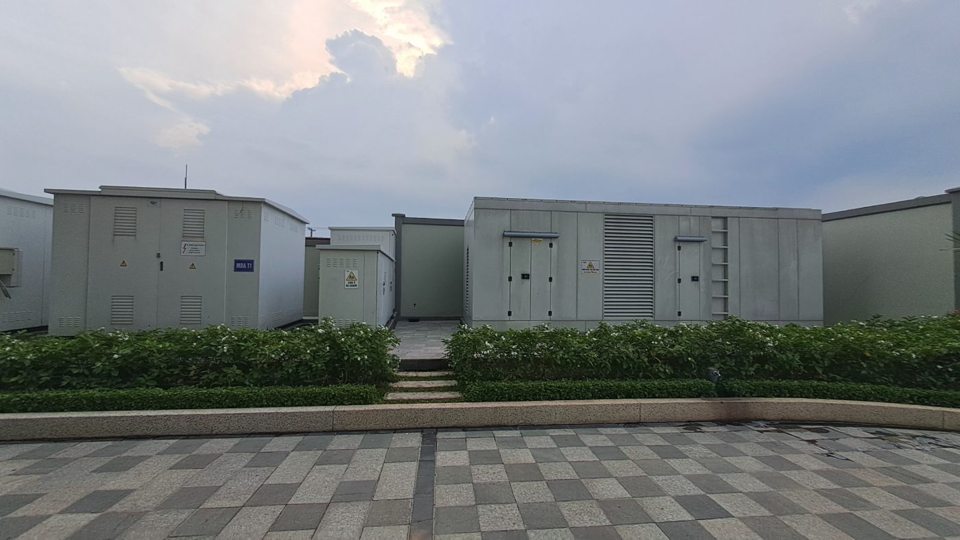
The kVA printed on a factory transformer is a poor starting point for purchasing an emergency generator. The transformer may carry hundreds of kilowatts of non-essential production that must stop during a utility outage, while a much smaller group of safe-stop and essential services must survive. Even within that essential group, the toughest event may not be steady full load: an individual pump starting after transfer can impose a voltage and frequency dip that a generator with apparently sufficient kVA cannot support acceptably.
This guide shows how to build a step-by-step generator sizing brief for an industrial facility in Vietnam, with a worked load table, a preliminary P/Q calculation, a switching sequence and supplier evidence required before selecting a set. It is intended for owner engineers and EPC procurement teams, not as a certified generator or ATS design.
Prepared for QuangAnhcons · Editorial focus: emergency LV supply and generator procurement · Source review 10 October 2026. All loads, motor characteristics and timing in the example are hypothetical.
Decide what genuinely needs power when the utility fails
The owner should distinguish continuous essential loads, safe-stop loads, fire/life-safety loads governed by the approved fire strategy, short ride-through loads supplied by UPS, and production loads that may be deliberately shed. Some processes need a controlled stop and can tolerate minutes without utility power; others may need uninterrupted control power but not their main motor. A standby generator cannot be selected until the production and HSE teams approve those categories. Do not assume that a factory’s existing transformer rating or main ACB size defines the emergency scope.
For each load, record the consequence of losing power, the maximum acceptable interruption, the permitted restoration order, and whether the device is already supported by a UPS or local battery. A generator started through an ATS normally has a transfer delay; a server, PLC or control system that cannot accept any interruption may require a UPS, and the UPS charger/recharge current may increase generator demand after restoration. Emergency egress, fire safety, smoke control or similar regulated systems must follow the actual approved safety strategy, not be added or removed on the basis of a generic blog example.
| Classification | Typical questions | What the decision controls |
|---|---|---|
| Uninterruptible controls | What is the maximum allowable interruption, and for how long? | UPS autonomy and transfer interface |
| Safe-stop process | How long must drives, valves or cooling run to reach a safe state? | Generator loads, sequence and duration |
| Continuous essential support | Which auxiliaries must run throughout the outage? | Steady essential P/Q and duty rating |
| Intermittent emergency equipment | Which motors may start after transfer? | Step-load response, motor-start tolerance |
| Non-essential production | Can this load stay isolated until grid restoration? | Hardwired shedding and manual/automatic restart logic |
The only defensible load list is one that has been checked against an operating narrative. A facility that operates three shifts, runs an exothermic process or has refrigerated storage will have different emergency decisions from a warehouse with a daytime packing line. In the RFQ, ask the owner to accept the list before generator vendors quote capacities and installation layouts.
Convert essential loads into a comparable P/Q envelope
A preliminary three-phase steady-state study aggregates active and reactive power separately. For a sinusoidal fundamental approximation, each load has Q=P×tan(arccos(PF)), and the simultaneous total is S=sqrt((ΣP)^2 + (ΣQ)^2). The nominal current for a balanced 400 V line-to-line supply is I≈S×1000/(sqrt(3)×400). These are arithmetic screening relations, not a generator motor-start model or proof of compliance with the current generating-set performance standard.
Consider the following hypothetical critical-load board serving an industrial production block. Motor powers stated in shaft kW are converted with the assumed efficiency and load fraction. The UPS/PLC group and packaged auxiliaries are given as electrical input because that is the information available at the boundary. The results below use the simultaneous running case, after transfer and after permitted restoration steps.
| Essential group | Hypothetical input definition | Running P (kW) | PF used | Q (kVAr) |
|---|---|---|---|---|
| PLC/UPS charger & process controls | 18 kW measured electrical boundary | 18.00 | 0.95 | 5.92 |
| Cooling pump | One 30 kW shaft motor, 100% load, η=0.91 | 32.97 | 0.85 | 20.43 |
| Ventilation fans | Two 15 kW shaft motors, 80% load, η=0.90 | 26.67 | 0.85 | 16.53 |
| Compressor for safe stop | One 22 kW shaft motor, 75% load, η=0.91 | 18.13 | 0.85 | 11.24 |
| Emergency lighting and security | 12 kW electrical input | 12.00 | 0.98 | 2.44 |
| Critical packaged HVAC / server support | 35 kW electrical input | 35.00 | 0.90 | 16.95 |
The illustrative steady totals are approximately P=142.77 kW, Q=73.50 kVAr and S=160.6 kVA at the assumed operating points. At 400 V balanced three-phase, I≈232 A. These numbers are independently checkable: the cooling pump alone uses 30/0.91=32.97 kW, and two fans use 2×15×0.80/0.90=26.67 kW. If all operating states are genuinely simultaneous, the generator must be evaluated against at least this steady case; an additional capacity margin can be specified by the owner but should not be used to hide missing starting data.
A catalogue 200 kVA generating set may appear adequate on a simple kVA ratio, but that is not a selection recommendation. A package may be rated differently for emergency standby, prime operation, site temperature, altitude, ventilation and permissible average loading. A nominal kVA rating says little by itself about the instantaneous kW that can be added in one step, acceptable voltage/frequency deviations, alternator reactances, excitation system or response to nonlinear rectifier loads.

Sequence the loads as events rather than only one number
The hardest case may occur in the seconds after ATS transfer, before engines and voltages settle. Request a signed sequence from both the process OEM and the generator supplier. For example, the PLC/UPS and security may remain supported through their own UPS while the generator starts. After its voltage and frequency have stabilized, lighting and controls transfer first. Fans and cooling pumps start separately; the compressor only starts after a delay and provided the running-pressure condition still requires it. The supplier must verify each permitted start against the generator’s transient capability.
| Event | Illustrative order, not an acceptance time | Required evidence | What can fail if ignored |
|---|---|---|---|
| UT-00: utility undervoltage detected | Before generating-set start | ATS detection/rejection logic and delay | False starts or nuisance transfer |
| GT-01: generator stable | Before load connection | Voltage/frequency readiness and protections | Transfer at unstable operating point |
| LD-01: controls, security and essential lighting | Step 1 | UPS topology, charging inrush and PF | Undetected high charger demand |
| LD-02: ventilation | Step 2 | Motor starts, VFD limits, interlocks | Voltage dip or drive trip |
| LD-03: process cooling pump | Step 3 | Locked-rotor or start profile, reduced-voltage method | Generator speed/voltage transient failure |
| LD-04: safe-stop compressor and critical HVAC | Later conditional steps | Automatic restart permissions, duty priority | Repeated starts, transient overload |
| RT-01: utility restored | After qualified grid return | ATS retransfer, neutral/earthing scheme | Unsafe parallel or uncontrolled restart |
The times should be supplied by the generator and control vendors for the actual equipment. Do not insert “15 seconds ATS” as if it were a statutory requirement. Each event also needs a failure outcome: if the cooling pump does not start, does the process stop safely or trip the entire generator? This is operational design, not a simple spreadsheet arithmetic question.
Why a steady-state current calculation does not predict a start
An induction motor’s locked-rotor current can be several times its rated running current under direct-on-line starting, but a fixed generic multiplier should not be applied to every drive. A soft starter changes the voltage/current relationship; a VFD changes both the input current profile and harmonic behaviour, and may limit torque during acceleration. A generator’s electrical source impedance, engine inertia, governor response, AVR/excitation system and load acceptance performance all influence transient behaviour. Obtain the motor/drive vendor start trace or parameters and the generator vendor’s accepted step-load chart for the proposed set and conditions.
A diesel generator also has site-level constraints: combustion air supply, room ventilation, acoustic/air-emission requirements, fuel autonomy, spill containment, maintenance access and local fire-safety interfaces. An isolated outdoor canopy set and a set inside a basement equipment room present different construction and permitting risks. None of those requirements can be inferred from the six-row steady load calculation alone.
Distinguish standby, prime and continuous duty clearly
A machine quote often states a kVA rating without an accompanying duty classification. Ask for the exact rating definition, reference power factor, rated frequency, ambient temperature, altitude, fuel type and permitted duty cycle. An emergency-only system may use a standby duty envelope, but a site that frequently runs on generator power during load shifting may require a different prime or continuous rating and additional operational planning. Do not assume a rating survives the move from factory test conditions to a hot industrial roof or poorly ventilated generator room.
The fuel and emissions calculation needs a specific engine consumption curve rather than kVA × a remembered constant. Likewise, UPS battery backup at load transfer cannot be replaced by the generator’s fuel tank autonomy. The former concerns seconds/minutes of uninterrupted support; the latter concerns extended running duration. Both must be specified separately and verified against the operating philosophy. If the generator is expected to synchronize with the utility, do not reuse an isolated ATS design as if paralleling were automatic or approved.
Electrical boundary checks for safe procurement
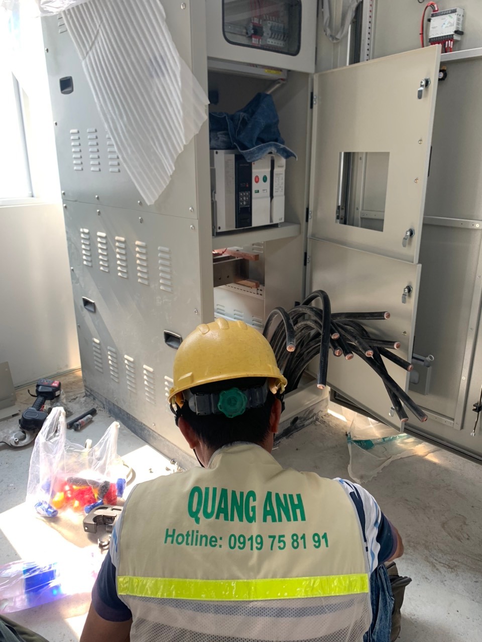
A standby source changes the effective fault-current envelope and the earthing/neutral path. Under generator operation, available short-circuit current at the remote DB may be much lower or decay differently than on a strong utility source. An overcurrent protective device sized solely for utility fault levels may not provide the expected clearing characteristics on the emergency source. Generator protective settings, ATS switching arrangements, residual current devices and PE/neutral bonding must be reviewed as an integrated design, with the permitted transfer mode documented.
Define whether the generator serves an essential MSB section, a dedicated emergency DB, or an ATS input upstream of several panels. Confirm feeder length, conductor installation method, voltage drop under motor starting, possible harmonic and unbalanced load, as well as grounding electrode and surge protection interfaces. Ask the local distribution utility or industrial-park seller which actions, if any, require coordination under the particular connection agreement. Do not invent an EVN-wide approval rule for all behind-the-meter generator installations.
For a project going to tender, the owner should request a load-step acceptance schedule: each permitted step, preceding running load, start/stop control, required voltage and frequency tolerance, guaranteed recovery condition, and the proposed witness test evidence. A quotation lacking this evidence is less mature than one backed by a vendor transient calculation—even if the first has a larger nominal kVA.
Acceptance and construction timeline: a practical framework
| Workstream | Input and decision | Dependency | Deliverable |
|---|---|---|---|
| Define essential operation | Owner/process/HSE approve load groupings | Pre-design | Essential load and safe-stop register |
| Agree ATS and UPS modes | Consultant, generator and controls suppliers | Load classification | Functional diagram and source interlock philosophy |
| Calculate steady and step demands | Supplier/OEM data and operating sequences | Real start traces | Generator candidate envelope and exclusions |
| Detailed design / vendor release | Fault cases, earthing, ventilation and civil layout | Approved sources and vendor data | Signed design, SLD and vendor submittal |
| FAT, delivery and site testing | Specific supplier plan and site interfaces | Product manufacture and installation | Test records, approved defects/closeout |
| Energization / handover | Operating documents and authorized inspections | Completion hold point | System training, as-builts, permits as applicable |
The equipment release point should be independent of the contractual project milestone. Promising a power-on date without confirmed permit and equipment availability does not make the programme reliable. A factory owner comparing proposals should require the bidder to state which values are firm guarantees and which are provisional assumptions pending testing.
Source and edition register (checked 10 October 2026)
| Source | Official scope and edition | Access level and limitation |
|---|---|---|
| ISO 8528-5:2025 | Generating-set design and performance, Edition 6 | Official ISO abstract and bibliographic record; no test class or clause copied from paid content |
| IEC 60076-1:2011 | Transformer general specifications | Official IEC catalogue; not generator load-step guidance |
| IEC 60909-0:2026 | Calculation scope for AC short-circuit current cases | Current edition catalogue checked; actual generator model not provided |
| OEM generator and ATS/UPS manuals | Equipment-specific transient duty and neutral/ATS arrangement | Must be furnished for exact models, revisions and site duty |
| Vietnamese TCVN/QCVN and utility/industrial-park documents | Project-specific supply, safety, environmental and installation obligations | Requires named jurisdiction and project; no invented rule or permit timetable |
Questions to put in the generator RFQ
Ask each vendor to return its rating basis and site correction factors, guaranteed step-load capacity at the proposed load sequence, tolerable voltage/frequency response, alternator/engine characteristics, ATS integration, protection philosophy, commissioning test plan, fuel and exhaust arrangements, warranty limits and an explicit exception register. Request a scenario change case if the owner wants the generator to run additional production equipment after several hours of outage. The new scenario may increase both steady P/Q and step-load demand; it cannot be dismissed by saying the transformer was originally sized with spare capacity.
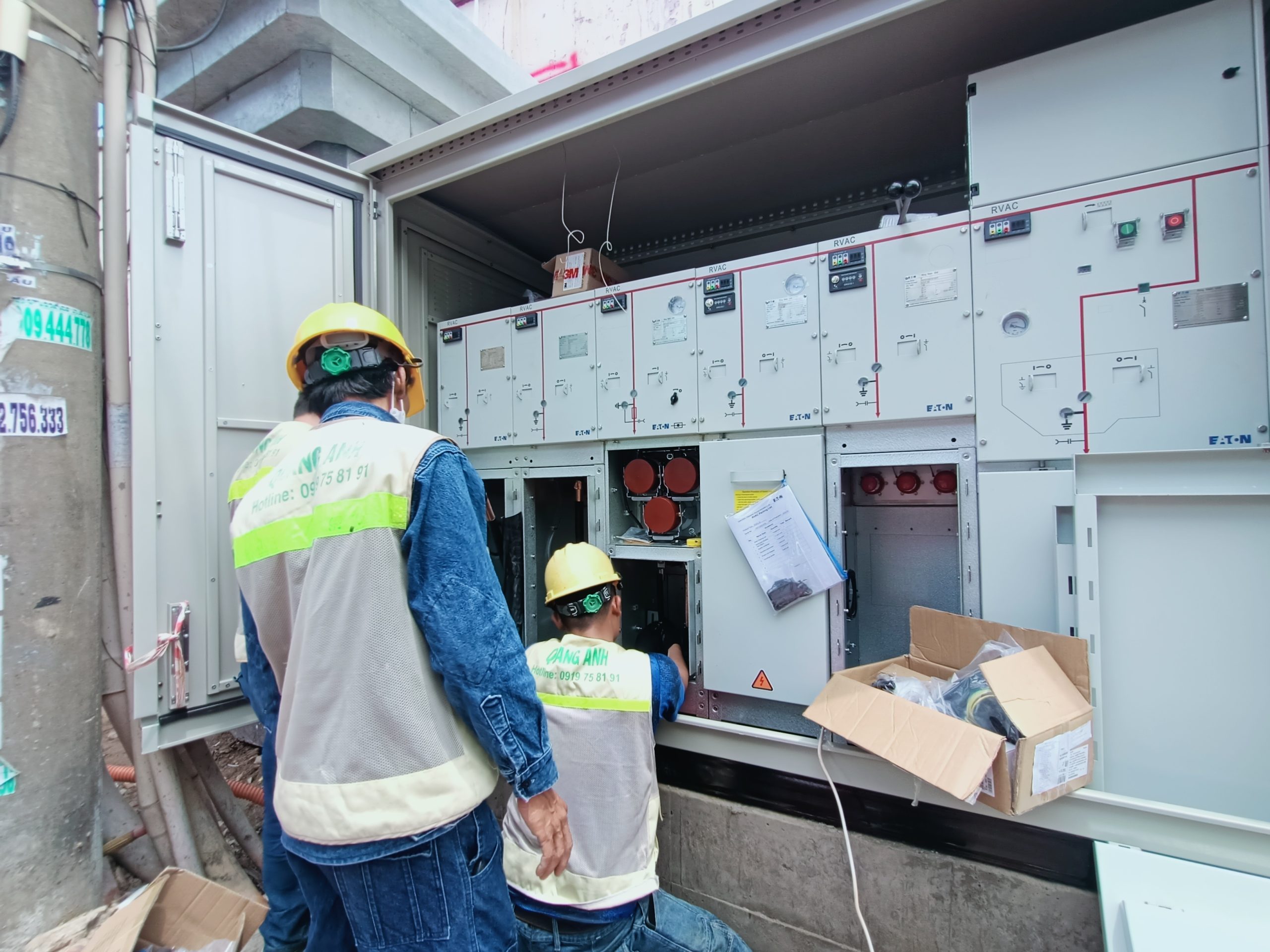
For factory power delivery context see our industrial electrical installations overview and factory electrical design responsibility matrix. The related QuangAnhcons construction video documents a factory substation energization activity, not a generator performance test or proof of the hypothetical load steps.
For an initial scope review, send the existing single-line diagram, operating philosophy, UPS loads, essential feeder list and OEM motor-start information to projects@quanganhcons.com or call +84 919 758 191. QuangAnhcons can help identify electrical interfaces and documentation gaps; final generator model and settings require the responsible designers’ and vendors’ project-specific verification.
[contact-form-7 id="7239967" title="Contact form 1"]
Related Posts
Size an industrial standby generator from essential-load steps, not transformer kVA
A factory standby-generator procurement guide with a worked six-group P/Q load example, transfer sequence, motor-start [...]
Oct
Before choosing breaker kA ratings: build a complete factory fault-case register
An electrical fault-case register separates maximum breaking duty from minimum-fault protection sensitivity, with documented grid, [...]
Oct
Imported production lines: turn motor ratings into an auditable factory P/Q load schedule
A worked industrial load schedule converts imported machine shaft kW to active and reactive demand, [...]
Oct
Long-Lead Electrical Equipment: Plan a Vietnam Factory Schedule
Plan long-lead electrical equipment for a Vietnam factory with release milestones, a backward schedule, site [...]
Oct
Who Owns Each Electrical Design Deliverable? A Responsibility Matrix for FDI Factories
Build an electrical design responsibility matrix for a Vietnam factory. Assign inputs, checks and approvals [...]
Oct
Before Leasing a Factory in Vietnam: Verify the Electrical Supply
Verify capacity, condition and landlord–tenant boundaries before leasing a factory in Vietnam. Use an evidence [...]
Oct
What Are You Really Buying in an Electrical EPC Tender?
Compare electrical EPC tender offers fairly. Use a scope matrix, worked bid example, RFQ wording [...]
Oct
Who Owns the Utility Connection? Responsibilities in a Vietnam Factory EPC Project
A decision guide for FDI factory owners in Vietnam: divide utility connection responsibilities among the [...]
May
Professional Electrical System Installation Process in Vietnam
As Vietnam’s industrial and urban sectors continue to grow, the need for reliable electrical system [...]
Aug
Find the Best Electrical Contractor Near Me – Your Reliable Partner
Finding a dependable electrical contractor near you is crucial for ensuring the safety and efficiency [...]
Jul
Top Vietnam Electrical Contractor Near You – QuangAnhcons
Finding a reliable electrical contractor is crucial for ensuring the safety and efficiency of your [...]
Jul
Top Vietnam Electrical Contractor Services – Choose QuangAnhcons
When it comes to ensuring the electrical safety and efficiency of your industrial facilities, finding [...]
Jul
Expert MEP Engineering for Industrial Buildings – QuangAnhcons
Efficient MEP (Mechanical, Electrical, and Plumbing) engineering is crucial for the optimal performance of industrial [...]
Jul
Trusted Electrical Contractors – Your Partner in Industrial MEP Solutions
In the rapidly evolving industrial sector, finding reliable MEP contractors is crucial. QuangAnhcons stands out [...]
Jul
MEP Construction Services for Factories – Comprehensive Solutions for Businesses
In the context of modern industry, MEP (Mechanical, Electrical, and Plumbing) construction services for factories [...]
Jul
Top-Notch Industrial Electrical Installation Services
Ensuring the optimal functioning of electrical systems in industrial settings is crucial for operational efficiency [...]
Jul
Professional Low Voltage Electrical Cable Installation and Cable Tray Construction – Enhancing Safety and Aesthetics
Upgrading your electrical systems is crucial for ensuring safety, efficiency, and aesthetics in any industrial [...]
Jul
Top-Quality M&E Construction Services – QuangAnhcons Vietnam
Professional M&E Construction Services – QuangAnhcons QuangAnhcons stands as a premier contractor in the Mechanical [...]
Jul