
This article focuses on practical steps for investors, project teams and M&E engineers to prepare substation interconnection documentation that minimizes the risk of delays in obtaining commercial power. It highlights the key information groups to gather, the contractor’s role in completing drawings and field checks, common pitfalls and concrete measures to reduce additional requirements when coordinating with the distribution utility. [1]
Substation interconnection documentation is the technical and legal package used to define the connection point, assess available capacity and schedule inspections/energisation. Missing or inaccurate items directly delay power supply timelines.
To reduce surprises, investors should prepare the main information groups early (capacity estimates, site location, grid status, single-line diagram and MV routing) and work closely with their contractor to finalise drawings and schedule field inspections.
- Connection documentation defines the connection point, required capacity and technical records to be checked — it directly determines when power can be supplied.
- Early preparation — site survey, capacity estimate, single-line diagram and MV routing plan — reduces requests for additions and scheduling delays.
- Contractor role: provide construction/connection drawings, propose technical solutions, assist with inspections and support handover with the distribution utility.
Who should read this?
- Investors and owners
- Manufacturing companies / Project offices
- M&E engineers
- Contractors building substations
When to read it?
- When planning a new substation or upgrading an existing one
- Before submitting an interconnection/energisation application
- When assigning responsibilities between investor, contractor and the distribution utility
Why connection documentation controls power-supply timing
The interconnection package defines the connection point, technical solution and conditions — so it directly affects the timing of technical review, field surveys and commercial energisation.

Connection documentation determines the power-supply schedule because it identifies the connection point, specifies the technical approach and forms the basis for the distribution company’s technical review. [6][8]
During a factory survey, the confirmation report issued by the distribution utility (PC/EVN) is the legal evidence that allows on-site inspection, grid capability checks and scheduling of equipment tests. Grid capability checks (present loading, remaining connection capacity, protection and operational conditions) are typically performed only after the technical dossier is submitted in full; their outcomes directly influence energisation timing and reactive power compensation requirements.
In practice, if documentation is incomplete or does not match field conditions (for example pole locations, cable types, substation position, equipment datasheets), the utility will request revisions, repeat surveys or adjust the connection plan. Missing acceptance records or test certificates for transformers, ACBs, isolators, surge arresters or earthing systems will halt acceptance and certification, delaying full power supply.
- Field checks: confirm substation/pole location, clearances, cable types and the actual connection point versus the drawings.
- Technical documentation required: complete drawings, equipment datasheets, field survey reports, connection confirmation minutes and test certificates.
- Legal requirements: conformity with land-use and planning approvals (Department of Industry & Trade), land-use rights certificates or construction permits when relevant for commercial connection.
- Distribution utility workflow: receive dossier → technical review → prepare draft connection agreement → sign (investors should verify the utility’s internal timeline).
Operational warning: changing the connection point after agreement will trigger supplementary surveys and renegotiation of schedules; during maintenance or when machines are running, any change in cable/substation routing must be communicated to avoid production interruptions. Investors should prepare field survey reports, connection confirmation minutes and equipment acceptance records before submitting the dossier to reduce revision cycles.
Next step: verify the applicability and currency of referenced guidance/ordinances and cross-check the field survey minutes with the distribution utility’s confirmation before finalising the official submission.
Information groups and documents typically required
The required documentation and field data usually include a capacity summary, single-line connection diagram, site coordinates and relevant legal paperwork.

The dossier should include a summary of demand, a single-line connection diagram, site coordinates (WGS84) and applicable legal documents before submitting the interconnection request. [3][0]
On site, provide survey photos (site plan, nearest poles/cables), a plot layout and elevation levels to verify the pole positions and MV route. During a factory survey confirm the distance to the nearest feeder/substation, the network topology (ring or radial) and mark the proposed connection point on a map with WGS84 coordinates.
From a technical perspective, include a load estimate table by equipment group (load name, actual kW, power factor, diversity/usage factors), peak and rated capacities, and a single-line diagram showing transformer, isolator, ACB/CB, busbar, standby transformer and any voltage regulation equipment (TSC/OLTC). If important data are missing — for example short-circuit current at the connection point or existing feeder loading — note this explicitly and coordinate with the distribution utility to obtain measured values or official data.
- Capacity summary: peak capacity, rated capacity, baseline and dynamic loads.
- Load estimate table by equipment group: actual P, power factor, diversity factor.
- Site location: address, WGS84 coordinates, plot layout and elevations.
- Survey photos: line/substation axes, existing poles/cables nearby.
- Area grid overview: adjacent voltage levels, network diagram, distance to distribution substation.
- Proposed connection details: grid owner, pole/feeder location for tapping.
- Single-line connection diagram and MV routing option (overhead/underground).
- Metering and monitoring requirements: meter location, CT/PT positions, measurement points, communications/SCADA needs.
- Access and safety information: protection corridor, required clearances, construction route.
- Project legal documents (if applicable): investment license, building permit, land-use documentation.
A high-level checklist can be presented in summary tables to ease pre-submission review. Technically, if the connection point changes during the survey, update the single-line diagram, recalculate load flow and provide short-circuit data to the utility — these factors determine switching capability and protection requirements.
| Item | Short description | Field note |
|---|---|---|
| Capacity summary | Peak, rated, baseline/dynamic loads | Validate with load schedule and check equipment descriptions on site |
| Single-line diagram | Transformer, isolator, CB, busbar, standby transformer | Mark the proposed connection point on the site plan |
| MV routing plan | Overhead or underground, cable/wire types, pole locations | Take photos of the route and record joint coordinates |
Operational warning: if the dossier lacks short-circuit data or existing feeder loading, the distribution utility usually requests additional measurements or a site re-survey, which delays the interconnection. After preparing the initial package, schedule a preliminary submission to the utility so they can verify grid capability and list any missing parameters before finalising the connection agreement.
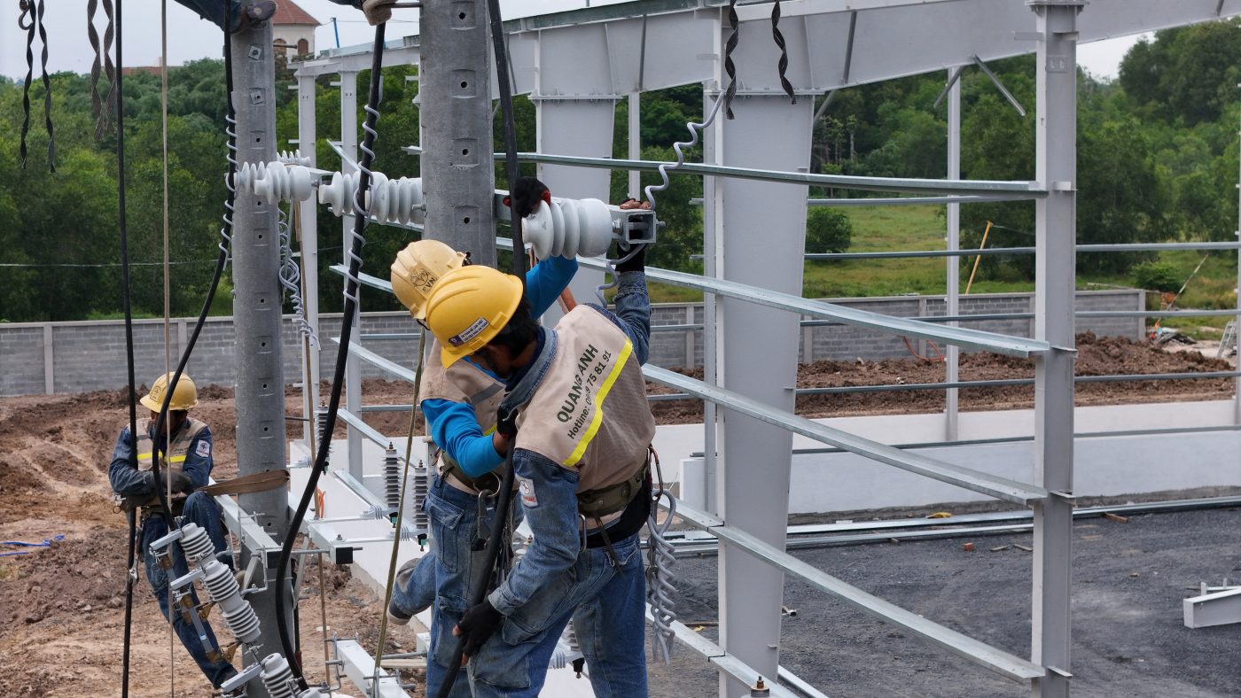
Contractor responsibilities in preparing documentation and coordinating acceptance
The contractor’s scope for interconnection dossiers includes field surveys, detailed design, testing, coordination for acceptance and handover with the distribution utility.

The contractor has primary technical responsibility for surveys, producing construction/connection drawings, performing tests and coordinating acceptance with the distribution utility. [5][0]
On site, the contractor must survey the MV route, the substation condition and feeder capacity, then propose circuit layouts and transformer siting. Minimum survey checks include meter locations, space for transformer foundations and earthing arrangement verification.
Drawings and documentation from the contractor should be separated into preliminary drawings for review and construction drawings for acceptance, along with an equipment list and technical specifications. Test documentation should include test logs, calibration records, equipment certificates and handover minutes prior to submission.
- Field survey package: connection coordinates, site photos, feeder capacity data.
- Drawings: connection diagram, earthing layout, cable routes, transformer foundation details.
- Acceptance documents: test procedures, insulation test reports, ratio and load tests, handover minutes.
The contractor must source test equipment and prepare test procedures, and coordinate switching schedules with the utility to carry out commissioning and acceptance tests. If the connection point changes after submission, the contractor must revise technical plans and resubmit for review — this can delay acceptance.
Responsibilities should be formalised with a written handover or scope-of-work record between the investor and contractor, specifying tasks, deadlines, acceptance criteria and who supplies load data. On quality and safety, the contractor is responsible for QC per contract and for following safe work procedures during construction, transmission and connection activities.
At the end of this stage, we recommend issuing a task handover record and a detailed survey schedule to lock in acceptance milestones: technical handover, construction completion, pre-acceptance tests and energisation acceptance.
Common risks in the interconnection process and mitigation measures
Typical interconnection risks include incomplete dossiers, connection-point changes, mismatched equipment and delayed inspections — and practical field mitigations are outlined below.

Common risks include incomplete dossiers, changes to the connection point, mismatches between design and equipment, and delayed inspections. [3][12]
On site, typical signs are missing signatures or as-built drawings, equipment types that differ from tender documents, and postponed inspection/energisation due to unclear coordination. During a factory survey check primary and backup meter positions and compare the equipment list on site with the technical dossier.
Mitigation measures include early written confirmation of the connection point and a meeting record; strict drawing version control; harmonising equipment lists in the tender package; and fixing inspection dates with a utility contact person. During maintenance windows or before first energisation, keep at least two copies of the acceptance package available at site for switching checks.
Below is a quick field-check table to identify risks before submission or to request amendments:
| Risk | Field check / criteria |
|---|---|
| Incomplete or incorrect dossier | Compare against a documentation checklist: signatures, drawings, equipment certificates, metering records |
| Connection point changed after submission | Check survey minutes, confirm coordinates/MCC/substation and have written agreement |
| Design — equipment mismatch | Verify nameplates, CT/CB/meter types and compare with procurement records |
Operational notes: changing the connection point without an agreement may force rework of acceptance schedules and additional tests; incorrect metering arrangements affect billing and acceptance. Therefore establish a clear utility contact and a fixed field-inspection schedule prior to energisation.
The logical next step is to perform a site survey using a checklist, update drawing versions and send written confirmation of the connection point to the distribution utility to avoid last-minute changes.
Practical checklist: preparing documentation to reduce add-ons
A complete MV interconnection package collects capacity data, site drawings, a single-line diagram, a survey report and a scheduled field inspection.

The checklist should bundle technical and legal documents to shorten interconnection processing times. [8][0]
Technically, the objective is to present capacity and connection diagrams clearly to minimise additional requests from the utility. During maintenance windows or surveys, include a signed field survey record with photos as evidence of grid status and the proposed MV route.
Below is a practical document list and verification criteria arranged in submission and field-check order.
- Capacity and load information: nameplate/rated power, short-term peak, diversity factor, phase distribution and load types; verify the load table during the site survey.
- Site drawings and layout: substation location on the map, site boundaries, proposed connection route and distances to adjacent structures; on site photograph markers and cable routes.
- Single-line connection diagram: indicate the proposed connection point, transformer, protection, metering and switching; check voltage compatibility and connection style at the point of interface.
- Field survey minutes: record date/time, participants, grid status at the connection point, cable/line condition and supporting photos; obtain signatures or on-site confirmation.
- Preliminary confirmation from the utility (if available): written agreement on the connection point or a meeting record; this significantly reduces the risk of changes after submission.
- Main equipment list and basic specs: transformer, isolator, CB, control cubicle, CT/VT with ratings, voltages, connection type and proposed protection; verify types against design documentation.
- Investor legal documents: company registration, formation/representative authorization, and land-use documents when the substation location involves land ownership issues.
- Timeline / acceptance schedule: submission dates, survey schedule, inspection window and expected acceptance/energisation dates; assign responsible contacts.
- Metering and meter location requirements: define primary and backup meter positions per the connection agreement; ensure the meter location is clearly marked on drawings for acceptance.
- Electrical safety & fire protection documents: safe work plan, protection of safety corridors and fire safety paperwork if the substation is indoors.
- Contingency plan: list common issues and escalation contacts, e.g., connection-point change or land clearance obstacles.
For submission, we suggest grouping files: technical, legal, utility confirmations and field schedule. At acceptance, prepare a provisional handover report and a list of any outstanding items to shorten administrative feedback time.
Operational caution: lacking preliminary utility confirmation or an unfixed connection point increases the likelihood of supplementary requests and delays. In practice, connection-point changes after submission result in redesign and extra costs.
Short conclusion: after assembling the items above, schedule a joint field survey with the distribution representative and prepare the single-line diagram and legal copies for submission.
Reference sources and verifying regulatory updates
Distinguish guidance from EVN/PC, Ministry of Industry & Trade circulars and national standards (QCVN/TCVN) from IEC/ISO technical standards — and verify effective dates and geographic scope.

Main references are EVN/PC guidance, Ministry of Industry & Trade circulars and QCVN/TCVN standards; IEC/ISO standards serve as technical references. [0][0]
Technically, EVN/PC documents typically include operational, safety and local requirements for interconnection work; circulars and QCVN/TCVN are national legal instruments that regulate procedures and technical standards. IEC/ISO should be used for design or test criteria only when domestic texts lack detail. During a site survey, identify the specific EVN/PC document that applies to the utility managing the connection point to avoid misapplying rules.
When preparing or commissioning, verify the publication and effective dates of every referenced document; current practice is to prioritise documents effective from 2024 onwards for procedural matters. If a reference lacks a clear effective date or predates 2024, contact the local PC/EVN to confirm its current validity before applying it.
- Field check: verify document code, issue date and issuing body during surveys.
- Define scope: confirm which EVN/PC regional guidance applies to the connection point.
- Resolve conflicts: if EVN/PC guidance conflicts with a circular, record the discrepancy and request written clarification from the competent authority.
Warning: do not base procedures on outdated documents; changes to the connection point or to guidance after submission can require revised technical plans and extend acceptance time. Complete document verification and the site survey before preparing the final dossier.
Submitting a complete interconnection package, with verified field conditions and a clear connection plan, combined with close cooperation between investor, contractor and utility, is the most effective way to reduce the risk of delayed power supply. Next step: prepare a summary of capacity, site coordinates and grid status to start the field survey.
Frequently asked questions
Which steps in the power-supply timeline are directly affected by the interconnection documentation?
The interconnection package directly affects: defining the connection point, assessing grid capability, preparing the technical plan, scheduling field inspections, signing the agreement and energisation. Missing information usually prompts supplementary requests and delays. Provide capacity data, a single-line diagram, survey records and legal documents.
When should a field survey be carried out to avoid supplementary requests?
Conduct the site survey early — before formal submission or immediately after capacity and site selection. The survey should record coordinates, photos, distance to nearest line/substation and transformer/meter locations; this reduces the risk of additional visits and delays.
Who is responsible for providing the single-line diagram and connection drawings?
Typically the contractor prepares the single-line diagram and connection drawings (preliminary for review, construction for acceptance). The investor supplies capacity requirements, legal documents and site confirmation. Responsibilities should be defined in the contract; if unclear, issue a scope handover before submitting the dossier.
What usually happens if the connection point changes after submission?
Changing the connection point after submission commonly requires supplementary documents, re-survey, design revisions and postponed inspection/energisation; it may incur additional costs and technical constraints. When changes occur, provide the reason, new coordinates, photos and an assessment of grid impacts for the utility’s review.
Are there official sources to reference for MV interconnection procedures in the local area?
Refer to the EVN/PC regional documents, Ministry of Industry & Trade circulars and QCVN/TCVN standards; each PC may issue regional guidance. Request documents that show effective date and scope; if needed, contact the PC region to obtain the latest list of applicable documents and URLs.
Practical steps to prepare a substation interconnection dossier
- Step 1 — Gather initial information: collect the required capacity (kW/kVA), load types, timing of demand and any future expansion plans.
- Step 2 — Conduct an early site survey: verify location, distance to MV lines, condition of poles/connection points and take photos of the grid at the proposed site.
- Step 3 — Work with the contractor to finalise drawings: request the single-line diagram, MV routing plan, site layout and preliminary construction drawings.
- Step 4 — Identify the provisional connection point and obtain preliminary confirmation from the distribution utility (local EVN/PC) before formal submission.
- Step 5 — Plan field inspections and the acceptance schedule: coordinate dates with the contractor and utility and agree the list of documents and equipment nameplates to be checked.
- Step 6 — Package the dossier for submission: include the capacity summary, drawings, field survey minutes, relevant legal documents (general list only) and technical data; track responses and prepare for supplementary requests if necessary.
Please send the project location, required capacity and a description of the current electrical feeding arrangement so QuangAnhcons can advise on how to prepare the interconnection documentation that fits your situation.
Reference sources (12)
Reference policy: prioritise official and traceable sources (EVN/PC regional guidance, Ministry circulars, QCVN/TCVN, and IEC/ISO/IEEE where relevant). Any procedural claim should link to an official document with an effective date (prefer references dated >= 2024 for regulatory content). Do not list mandatory dossier items without citing an official source; when using local guidance (provincial PC/EVN), cite the URL and specify the region of applicability.
-
tcvn.gov.vn
Official source from tcvn.gov.vn used to verify technical information or referenced regulations.
-
National standards planning document
Official document from tcvn.gov.vn for cross-checking technical statements and regulations.
-
EVN guidance PDF | Interconnection/metering templates | EVN | 2020
Official EVN source referenced for interconnection and metering procedures.
-
Customer service circular 2025: distribution and metering regulations
Official circular from EVN HCMC customer service portal.
-
EVN news item on approved project procurement plans
Official EVN news item used for background reference.
-
EVNSPC regional guidance or template
Official EVNSPC source referenced for technical or procedural checks.
-
EVNSPC regional document
Regional EVNSPC guidance used as a reference.
-
EVN news: inspection of selected projects
EVN news item used to support process context.
-
Ministry circular on operational control and restoration
Ministry of Industry & Trade announcement used for regulatory context.
-
Ministry article on tariff framework for small renewables
Ministry source for policy context.
-
Draft circular on electrical infrastructure protection and safety
Draft circular used as a planning reference.
-
EVN: generation plants not required to pay MV connection fees under certain investments
EVN notice referenced for connection cost context.
Related Posts
Substation Interconnection Documentation: A Practical Preparation Guide for Investors
A hands‑on guide for investors and M&E engineers on the information groups needed in substation [...]
May
Transformer Substation Construction Quote: Cost Components & Key Cost Drivers
Guidance for breaking down a transformer substation construction quote: main cost groups and the common [...]
May
Substation Solutions for Factories: Investing and Implementation Strategies
Overview of factory substations: when to invest, key components, execution processes, documentation, and selecting the [...]
Apr
Transformer Repair in Ho Chi Minh City: When Immediate Action Is Required
Discover signs of transformer damage, diagnostic methods, on-site handling processes, and criteria for selecting repair [...]
Apr
Transformer Repair: Process, Diagnosis, and Decision-Making
Hướng dẫn sửa chữa máy biến áp cho nhà máy: nhận biết dấu hiệu hỏng, [...]
Apr
24-Hour Transformer Repair: Efficient Solutions and Reliable Power Restoration
Khung xử lý sửa chữa máy biến áp 24h cho nhà máy: nhận biết sự [...]
Apr
Common Mistakes in Transformer Station Construction Leading to Extra Costs
Các sai lầm khi làm trạm biến áp thường không nằm ở một hạng mục [...]
Apr
Comprehensive Guide to Acquiring Used Transformers
Góc nhìn kỹ thuật về thu mua TBA cũ: cách đánh giá hiện trạng, hồ [...]
Apr
Comprehensive Transformers Maintenance for Industrial Plants
Tổng quan dịch vụ bảo trì trạm biến áp nhà máy: lịch bảo dưỡng, thí [...]
Apr
Transformers: Assessing and Safely Handling Used Transformers
Khung đánh giá máy biến áp cũ theo tình trạng kỹ thuật, dầu cách điện, [...]
Apr
How Proactive Transformer Maintenance Minimizes Business Risks
Nhìn từ góc độ vận hành nhà máy, bảo trì chủ động trạm biến áp [...]
Apr
Comparing Oil and Dry Transformers in Industrial Projects
Distinguish between oil and dry transformers based on installation site, safety, maintenance, energy losses, initial [...]
Mar
Electrical Overload Warning Signs in Factories
Recognize early indicators of factory electrical overload such as voltage drops, overheating equipment, circuit breaker [...]
Mar
Risks of Overloading Industrial Transformers Without Upgrades
Keeping the same low-voltage transformer while increasing factory loads can result in overheating, insulation degradation, [...]
Mar
Evaluating and Implementing Transformer Contractors in Tay Ninh
Criteria for selecting transformer substation contractors in Tay Ninh, EPC scope, and factors affecting project [...]
Mar
Comparing Oil and Dry Transformers for Industrial Applications
Examine oil and dry transformers based on installation location, fire safety, maintenance, energy loss, investment [...]
Mar
Comprehensive 1500kVA Transformer Station Budget for Manufacturing Facilities
Guidance for creating a detailed budget list for a 1500kVA transformer station, including medium voltage [...]
Mar
Comprehensive Transformer Station Pricing: Elements and Considerations
Examine key components in comprehensive transformer station pricing including design, equipment, construction, testing, and connection [...]
Mar
Pricing Guide for 4000kVA Transformer Stations: Configuration, Cost, and Investment Process
An overview of configuration, cost estimates, connection approaches, and investment checklists for 4000kVA transformer stations [...]
Mar
Pricing and Setup of 3200kVA Transformer Stations: Configuration, Costs, and Investment Procedure
Explore the pricing structure for a 3200kVA transformer station, primary equipment configuration, cost variables, EVN [...]
Mar