

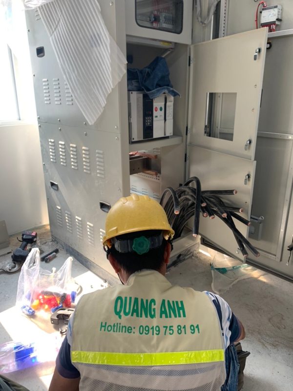
A breaker catalogue may offer several interrupting ratings for the same nominal current. Selecting the model by comparing one transformer nameplate or one remembered short-circuit number is not a defendable fault-duty study. The prospective short-circuit current depends on the grid supply, transformer impedances, network topology, connected rotating machines, converter contributions and which sources are allowed to operate together. The minimum fault current at the remote end of a feeder matters too, because a protection device must detect and clear credible faults under adverse supply conditions.
This guide explains how an FDI factory owner or electrical package manager can prepare a case register for an IEC 60909 engineering study before asking bidders to nominate ACB/MCCB or MV switchgear interrupting ratings. It supplies an example network, independent screening calculations, data boundaries and an approval checklist. This is a teaching example—not a complete IEC calculation, certified setting sheet or permission to energize equipment.
Prepared for QuangAnhcons · Editorial focus: short-circuit input cases and switchgear procurement · Sources reviewed: 10 October 2026. Every example impedance and source value is an explicit hypothesis.
Define the network and its switching states before discussing fault current
Draw the real electrical network from the contractual point of common coupling to the machine terminals. A common industrial arrangement contains a 22 kV supply feeding MV protection, one or more 22/0.4 kV transformers, an LV main switchboard, optional normally open bus ties, an emergency generator, motor feeders and—on some projects—PV or BESS inverters. The diagram needs an equipment ID at each bus, the approved normal switching position and every operationally permitted contingency. A drawing without operating states cannot establish the fault sources which may actually be connected.
A factory with two transformers and a bus tie is especially sensitive to incorrect assumptions. If the tie remains open, a fault on one LV section sees its own transformer and contributions from connected motors or converters. If an authorised operating mode closes the tie, contributions from another section may become possible. Conversely, a generator feeding an electrically isolated emergency board through a transfer switch may never operate in parallel with the utility. Drawing both sources on the same page does not mean their short-circuit contributions can be added: the ATS interlocking, approved sequence and actual fault path govern.
| Bus or feeder | Upstream source paths | Allowed switch states | Required evidence |
|---|---|---|---|
| 22 kV incoming PCC | Utility or licensed industrial-park distributor | Normal supply, declared alternatives | Maximum/minimum short-circuit power or Thevenin source data and X/R |
| Transformer A LV terminals | MV source via transformer A | MV device closed, LV ACB closed | Transformer rated data, guaranteed impedance, tap position |
| Transformer B LV section | Transformer B and possibly A through tie | Tie open versus authorized transfer | Electrical interlocking and closed-tie permission |
| Generator emergency bus | Generator and emergency motor feeders | Isolated island; no assumed grid parallel | Generator subtransient and control data, ATS diagram |
| PV/BESS feeder | Current-limited converters under real modes | Grid-connected, islanding if genuinely supported | Verified fault contribution and operating mode documents |
| Remote production DB | Feeder cable and local connected loads | Longest/lowest-fault path | Cable impedance, temperature, neutral/PE path and protection time |
A case register is not just a matrix of switches. It must say why the case exists and which equipment it is intended to stress. The maximum prospective current may govern breaking capacity and initial peak making duty; a minimum source case may govern protection sensitivity or earth-fault disconnection. Arc-flash assessments, touch-voltage safety, motor withstand and specific insulation duties require additional analyses. Do not conflate those acceptance questions into one column labelled “fault current OK”.
Gather source impedance—not merely transformer kVA
For an initial order-of-magnitude check at the transformer LV terminals, engineers sometimes use the simplified relation I_k ≈ I_n × (100/u_k%) under a stiff-source approximation. Here I_n = S_n /(sqrt(3) × U_LL) and u_k% is transformer short-circuit impedance expressed in percent. This rule of thumb intentionally ignores the upstream grid impedance, voltage factors, resistance/reactance separation, motor and converter contributions, and the detailed maximum/minimum modelling required by IEC 60909-0. It therefore cannot justify a breaker rating or protection setting by itself.
Take a hypothetical 1,600 kVA, 22/0.4 kV transformer with a declared impedance of 6%. The idealized rated LV current is 1,600,000 / (sqrt(3) × 400) = 2,309 A. The stiff-source transformer-only screening result is 2,309 / 0.06 = 38.49 kA. It would be unsafe to state that the factory’s maximum available three-phase fault current is exactly 38.49 kA. The actual number is conditioned by source short-circuit strength, maximum voltage, tap position, conductor and busbar impedances, contributions from motors and converters, and the calculation method used by a competent engineer.
As a sensitivity illustration, applying the same approximation at 5% and 7% transformer impedance gives approximately 46.19 kA and 32.99 kA. The large movement across this narrow input band shows why a transformer procurement datasheet needs the supplier’s guaranteed impedance and tolerances, rather than a default number inserted by the estimator. Even this three-case comparison is insufficient for minimum-fault protection checks because it does not model remote feeder impedance or line-to-earth return paths.
Distinguish breaking duty, making duty and short-time withstand
A prospective initial symmetrical RMS short-circuit value and a breaker catalogue’s rated ultimate breaking capacity are not a complete coordination proof. The project must separately check the relevant breaking and service capacities at the correct voltage, the peak making/withstand duty, operating time, upstream/downstream selectivity or back-up protection, and any constraints imposed by the switchboard assembly verification. An MCCB with an impressive kA label may still be unsuitable for a particular circuit due to installation conditions, product series, coordination assumptions or application details.
Ask switchgear suppliers for exact model references and corresponding technical documents. Many device ratings change with applied voltage, pole configuration, AC/DC application, temperature and product variants. An upstream ACB and downstream MCCB combination may have tested selectivity or cascading tables, but those claims are valid only for the specified pair and arrangement. A generic statement “all breakers are IEC compliant” is not a substitute for the documented device/assembly combination that will actually be installed.
Example case register for a factory with utility, generator and PV
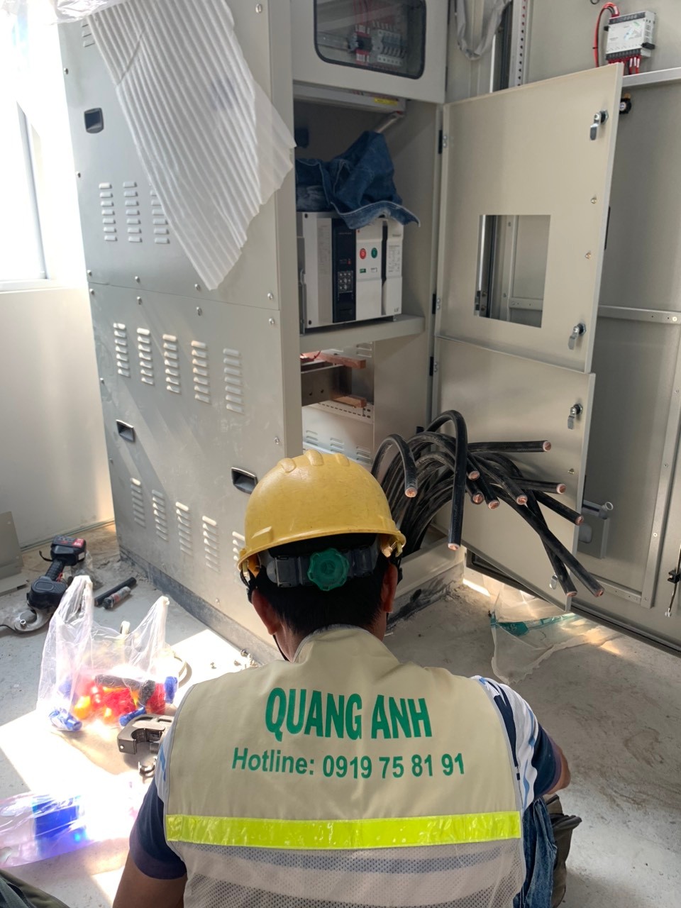
The following register describes a fictitious factory with one 1,600 kVA transformer, an LV MSB, an emergency diesel generator isolated from the grid under approved ATS controls, and a rooftop PV inverter feeder. These are case definitions, not verified numerical outputs. Replace every “to be obtained” field with actual utility and vendor data before the system study is signed off.
| Case ID | Configuration | Fault location / type | Engineering question | Evidence still needed |
|---|---|---|---|---|
| SC-01 | Utility max, production motors running, PV grid-connected | MSB three-phase | Peak/breaking duty at transformer LV bus | Utility maximum source, R/X, exact motors and converter current data |
| SC-02 | Utility min, low voltage, feeders hot | Remote DB L–L and L–PE as applicable | Can the feeder protection detect/clear minimum credible faults? | Minimum source, cable R at temperature, PE/neutral loop, trip curves |
| SC-03 | Utility absent; diesel island via ATS | Emergency DB three-phase and earth faults | Is available generator fault current sufficient for the selected protection? | Alternator subtransient and decrement curves, AVR support, ATS neutral |
| SC-04 | Utility max, PV offline for maintenance | MSB three-phase | Sensitivity to converter connection | Validated inverter contribution model and switching constraints |
| SC-05 | Allowed maintenance/transfer topology | Tie or alternative feeder boundary | Does one additional source path change duty? | Signed one-line, mechanical/electrical interlocks and authorization |
| SC-06 | Minimum-source conditions plus long route | Final production DB | Disconnection under the least favourable credible conditions | Actual route length, conductor material/cross-section and return path |
Crucially, do not activate a hypothetical “generator + utility closed tie” case simply because the spreadsheet offers such a combination. If parallel operation is not part of the approved design, mark it prohibited, not a valid running state. Conversely, if the plant has a closed-transition transfer or intentional parallel arrangement, omission of that real operating case creates a dangerous evidence gap.
Calculate independently without pretending a screening example is a study
At 400 V and 1,600 kVA, the rated current calculation should be independently reproduced to ensure the units are correct. Checking sqrt(3) × 400 V × 2,309 A ≈ 1.60 MVA catches common thousand-fold errors when one spreadsheet cell uses kV and another uses V. A second check varies the transformer impedance input across the expected procurement tolerance, and a third check compares the simplified terminal screening current with the independently modelled detailed result. These checks can reveal bad inputs; they do not validate the entire model.
A remote fault is not necessarily the worst current for all purposes. Cable impedance usually reduces current as distance increases, whereas low enough current can challenge an overcurrent protective device’s sensitivity. In a TN system, the phase-to-protective conductor return route and disconnection requirements are important; a TT arrangement has a different earth-fault protection basis. Do not make a design claim about the PE or RCD arrangement without an approved earthing schematic and measured or validated parameters.
For a grid-following inverter, the power-electronics controller may limit current and alter behaviour within cycles. The source cannot be modelled as if it were a synchronous alternator with the same rated kVA. The manufacturer must provide current-limiting and ride-through behaviour for the model, firmware and operating mode actually being supplied. The resulting treatment belongs in the project’s selected version of the applicable short-circuit methodology and related device verification.
Connect the study cases to procurement and commissioning
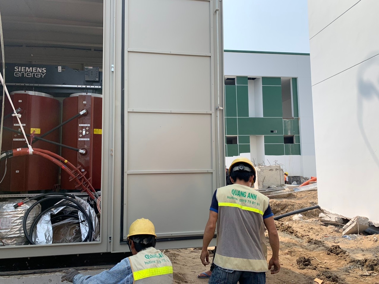
The project engineer should build a decision table connecting each case to required engineering deliverables. Use one row per device duty: for example MSB ACB — SC-01 — calculated fault quantity — selected model — voltage-specific breaking data — panel assembly evidence — reviewer — status. For a remote DB the controlling case may be SC-02 or SC-06, with device trip curve and earthing loop information. For the generator feeder another case may govern. Keep the database updateable as the machine supplier changes motor data or the owner revises the switching arrangement.
A purchase order should not release final switchgear ratings solely because a preliminary load-flow chart was accepted. Load current, voltage drop, short-circuit withstand and protection discrimination are separate acceptance paths. Identify a hold point for the fault study, another for device/assembly submittal approval, a site test plan for instrument/relay functionality, and a witness record for the approved switching interlocks. A planned factory date is not permission to energize an unverified network.
| Hold point | Responsible producer | Required evidence | Decision |
|---|---|---|---|
| FP-01 | Owner / supply interface | Current utility data and valid topology | Freeze source envelope or record limitation |
| FP-02 | Electrical designer | Versioned maximum and minimum case results | Approve study basis for equipment selections |
| FP-03 | Equipment vendor / designer | Model-specific Icu/Ics/Icw/peak and panel verification as applicable | Accept or reject candidate equipment |
| FP-04 | Protection engineer | Discrimination/disconnection and setting report | Review coordination with actual curves |
| FP-05 | Test/commissioning parties | Approved procedures, calibration and site witness records | Authorize the next commissioning hold point |
If one of these records is missing, the matrix should identify who owns the unresolved item and the date required for a commercial decision. A status labelled “provisional for budget” should not be recast as a released construction design.
Standards and primary source register
| Reference | Verified catalogue scope, edition | What has not been claimed |
|---|---|---|
| IEC 60909-0:2026 | IEC official publication dated 23 July 2026, Edition 3.0; short-circuit current calculation in AC systems | Full standard text was not used to certify example values; no clause numbers invented |
| IEC 60076-1:2011 | Transformer general requirements, IEC catalogue Edition 3.0 | No thermal/impedance compliance statement about an unknown transformer |
| IEC 60364-5-52:2009+A1:2024 | LV wiring systems, official consolidated catalogue | No unverified conductor ampacity or voltage-drop limit applied |
| Manufacturer breaker and assembly guides | Model-specific interrupting, making, withstand and coordination data | Catalogue family names do not prove an actual device/combination is selected |
| Applicable Vietnamese TCVN/QCVN and connection agreement | Local design, safety and distribution interface | Must be confirmed for named project, seller and equipment before design release |
Practical RFQ, related work and next steps
When issuing an RFQ to electrical contractors or equipment suppliers, include the case register, the known source data, what operating arrangements are permitted, the list of missing values and the deadline for clarification. Ask bidders to quote an engineering deliverable, not only a breaker catalogue. A helpful tender return should include the assumptions file, fault-case list, equipment-specific duties, coordination/verification records and a list of calculations to be re-run after actual OEM datasheets arrive.
For the responsibility split, consult the factory electrical design responsibility matrix. For procurement release points, see the long-lead equipment schedule guide. For physical LV cable interfaces and installation methods, our industrial electrical installation overview describes the surrounding work package. These links address different aspects of the decision; they are not substitutes for signed project data.
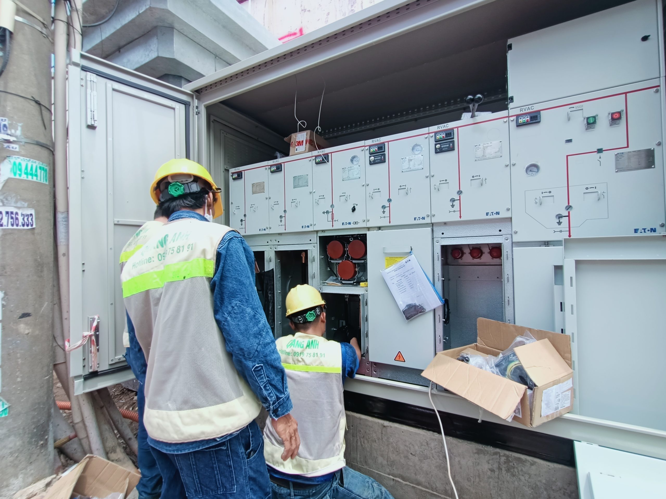
The QuangAnhcons factory energization video archive provides context about real substation installation and handover. It does not demonstrate that the hypothetical fault network above is safe or that the numerical screening results meet IEC 60909-0.
To review a source/fault study scope for a factory in Vietnam, send the single-line drawing, agreed supply interface, transformer and generator guaranteed data, machine list and protected-feeder schedule to projects@quanganhcons.com. Any proposed device duty or setting remains subject to project-specific electrical engineering and the approved commissioning process.
[contact-form-7 id="7239967" title="Contact form 1"]
Related Posts
Before choosing breaker kA ratings: build a complete factory fault-case register
An electrical fault-case register separates maximum breaking duty from minimum-fault protection sensitivity, with documented grid, [...]
Oct
Imported production lines: turn motor ratings into an auditable factory P/Q load schedule
A worked industrial load schedule converts imported machine shaft kW to active and reactive demand, [...]
Oct
Long-Lead Electrical Equipment: Plan a Vietnam Factory Schedule
Plan long-lead electrical equipment for a Vietnam factory with release milestones, a backward schedule, site [...]
Oct
Who Owns Each Electrical Design Deliverable? A Responsibility Matrix for FDI Factories
Build an electrical design responsibility matrix for a Vietnam factory. Assign inputs, checks and approvals [...]
Oct
Before Leasing a Factory in Vietnam: Verify the Electrical Supply
Verify capacity, condition and landlord–tenant boundaries before leasing a factory in Vietnam. Use an evidence [...]
Oct
What Are You Really Buying in an Electrical EPC Tender?
Compare electrical EPC tender offers fairly. Use a scope matrix, worked bid example, RFQ wording [...]
Oct
Who Owns the Utility Connection? Responsibilities in a Vietnam Factory EPC Project
A decision guide for FDI factory owners in Vietnam: divide utility connection responsibilities among the [...]
May
Professional Electrical System Installation Process in Vietnam
As Vietnam’s industrial and urban sectors continue to grow, the need for reliable electrical system [...]
Aug
Find the Best Electrical Contractor Near Me – Your Reliable Partner
Finding a dependable electrical contractor near you is crucial for ensuring the safety and efficiency [...]
Jul
Top Vietnam Electrical Contractor Near You – QuangAnhcons
Finding a reliable electrical contractor is crucial for ensuring the safety and efficiency of your [...]
Jul
Top Vietnam Electrical Contractor Services – Choose QuangAnhcons
When it comes to ensuring the electrical safety and efficiency of your industrial facilities, finding [...]
Jul
Expert MEP Engineering for Industrial Buildings – QuangAnhcons
Efficient MEP (Mechanical, Electrical, and Plumbing) engineering is crucial for the optimal performance of industrial [...]
Jul
Trusted Electrical Contractors – Your Partner in Industrial MEP Solutions
In the rapidly evolving industrial sector, finding reliable MEP contractors is crucial. QuangAnhcons stands out [...]
Jul
MEP Construction Services for Factories – Comprehensive Solutions for Businesses
In the context of modern industry, MEP (Mechanical, Electrical, and Plumbing) construction services for factories [...]
Jul
Top-Notch Industrial Electrical Installation Services
Ensuring the optimal functioning of electrical systems in industrial settings is crucial for operational efficiency [...]
Jul
Professional Low Voltage Electrical Cable Installation and Cable Tray Construction – Enhancing Safety and Aesthetics
Upgrading your electrical systems is crucial for ensuring safety, efficiency, and aesthetics in any industrial [...]
Jul
Top-Quality M&E Construction Services – QuangAnhcons Vietnam
Professional M&E Construction Services – QuangAnhcons QuangAnhcons stands as a premier contractor in the Mechanical [...]
Jul