

Executive answer. A pair of 2,500 kVA transformers and a normally open low-voltage bus-tie do not automatically give a factory full N−1 resilience. The defensible test is whether either transformer, after the other source has been safely isolated, can carry the explicitly designated surviving loads through an approved switching path, without violating transformer thermal limits, incomer and tie ratings, protection coordination or production priorities. If the total site load is too high, a documented load-shedding sequence is part of the architecture—not a defect to hide in the sales proposal.
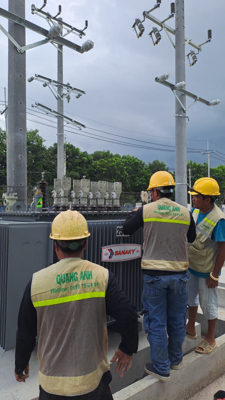
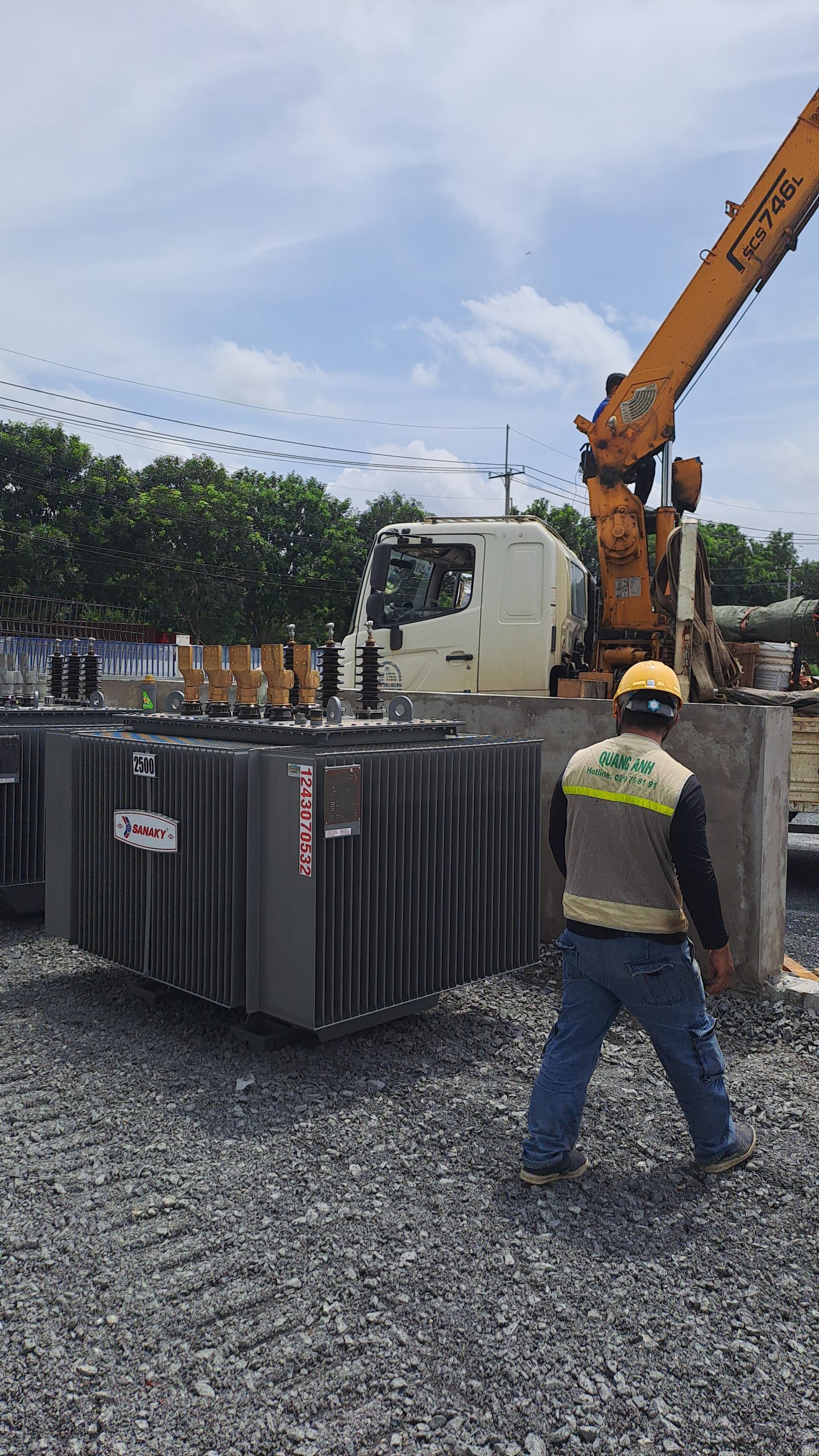
Engineering note by QuangAnhcons, 10 October 2026. All power figures and equipment ratings in the worked example are hypothetical screening inputs, not as-built data, guaranteed capacities, settings, or commissioning results for an actual client. The photography is generic QuangAnhcons website archive material and does not depict the illustrated two-transformer bus-tie topology.
What N−1 means when the bus-tie is normally open
A factory may have two transformers because loads are separated geographically, because the load exceeds one practical unit, or because the owner wants resilience. Those motivations are not interchangeable. With a split main switchboard, Transformer A feeds Bus A and Transformer B feeds Bus B; the bus-coupler is normally open. Under normal operation the transformers are not operating in parallel at low voltage. The coupler is a conditional transfer path, not an extra energy source.
In the owner’s specification, full N−1 should mean the specified total load is preserved following the loss of one defined component for the stated duration. Partial N−1 means named essential loads survive while identified loads are shed. Some facilities only require a manual restoration arrangement, not uninterrupted supply. Write this distinction into the RFQ before asking vendors whether an installation is “N−1 ready”. Schneider Electric’s public Electrical Installation Guide describes normally open coupled transformer arrangements as a possible way to improve supply availability, not an unconditional guarantee of continuity.
MV-A → Transformer A → LV Incomer A → [BUS A] ── (NO BUS TIE) ── [BUS B] ← LV Incomer B ← Transformer B ← MV-B
                                  │                             │
                            A feeders / load                B feeders / load
                           selected essential                selected essential
                           loads for transfer                loads for transfer
This is a functional concept diagram, not a wiring diagram or approved single-line diagram (SLD). The two medium-voltage sources may share the same upstream point of common coupling, so the apparent two-transformer topology may still have a common-mode utility failure. Confirm MV source independence and fault zones before calling the scheme redundant.
Start with the right design basis, not a transformer count
The minimum pack includes an as-built SLD with breaker positions; transformer serial numbers, vector groups, tap positions, impedances, thermal data and cooling mode; exact cable and busbar routes; the switchgear assembly manufacturer’s rating and temperature-rise evidence; a current and future P/Q load schedule by bus section; essential-load priorities; maximum and minimum fault contributions; source restoration rules; and the local electricity supplier’s approved interface requirements. Where production loads have variable power factor, an arithmetic sum of individual machine kVA is not a reliable replacement for a time-aligned P/Q calculation.
The owner must also define what event N−1 covers: failure of Transformer A, failure of Transformer B, their LV incomers, upstream MV disconnection or one distribution section. A fault on a busbar is not equivalent to an orderly loss of an incoming transformer. Closing the tie into a faulted bus can extend an outage and is prohibited unless a proven protection-and-isolation design specifically permits it. A low-voltage busbar sectionalizing design should therefore have a fault-zone diagram, not merely a pair of incomer breakers connected by a line in CAD.
| Design input | Illustrative example | Verification required before design release |
|---|---|---|
| Transformer units | 2 × 2,500 kVA, 22/0.4 kV | Guaranteed rating and thermal/ambient conditions; actual vendor data |
| Normal bus arrangement | Two separate LV sections, normally open tie | Approved SLD, operating authority and interlock truth table |
| Nominal LV voltage | 400 V three-phase | Site meter values, worst voltage and voltage drop |
| Contingency planning limit | 2,250 kVA on the surviving transformer | Assumed conservative project limit only; not IEC’s prescribed derating |
| Candidate tie rating | 2,000 A for evaluated essential-load transfer | Actual assembly verified rating, short-circuit duty, cabling, selectivity |
| Essential-load policy | Only listed process and life-safety-dependent functions | Owner/production agreement, restart and operating priorities |
The 2,250 kVA contingency limit is deliberately set by this example as 90% of nameplate for preliminary margin. No standard says every 2,500 kVA transformer is automatically limited to 2,250 kVA under N−1. An engineering study must derive permitted loading from the actual mineral-oil or dry-type equipment, ambient temperature, pre-load history, cooling, duration and vendor guarantees. Conversely, do not assume a short-time overload is permissible merely because a general loading guide discusses it.
Calculate normal P, Q, kVA and phase current
Consider two low-voltage production sections with different power factors. The symmetrical three-phase screening relationship is S = P / PF, Q = P × tan(acos(PF)) and I = S / (√3 × VLL), where P is kW, Q is kVAr, S is kVA and VLL is kV. It is important that a row’s PF is measured or defensibly estimated over the same time interval as its P. Mixing a motor nameplate PF with an unrelated site peak produces fictitious coincident kVA.
| Normal operation | P (kW) | PF | Q (kVAr) | S (kVA) | At 400 V (A) |
|---|---|---|---|---|---|
| Bus A on Transformer A | 1,320 | 0.90 | 639 | 1,467 | 2,117 |
| Bus B on Transformer B | 1,170 | 0.85 | 725 | 1,376 | 1,987 |
| Site coincident total | 2,490 | 0.877 aggregated | 1,364 | 2,839 | 4,098 equivalent |
Both sections are below 2,500 kVA individually. The last row does not mean 4,098 A flows through one incomer during normal operation: it is the equivalent combined apparent power divided by the same nominal voltage. Because the normally open tie prevents LV paralleling, the actual incomer currents remain near 2,117 A and 1,987 A under the stated symmetrical assumption. The combined site’s apparent demand is calculated by vector addition: √(2,490² + 1,364²) ≈ 2,839 kVA. This is higher than 2,500 kVA, which immediately invalidates a full-load single-transformer restoration claim under the example’s thermal limit.
Recalculate the load model for each operating case instead of using only a monthly energy bill. Important cases include normal high production, shift change, low production with capacitors active, starting large motors after supply restoration, seasonal ventilation load, generator transfer and later manufacturing expansion. The contingency peak might not align with the normal peak; that uncertainty should be stated rather than hidden behind a single diversity factor.

Prove both N−1 cases and specify load shedding
Now label the loads that must remain energized after a transformer is lost. For the example, the owner selects 980 kW at PF 0.92 on Bus A and 620 kW at PF 0.90 on Bus B. These are not generic percentages. They represent an explicit emergency-load register whose feeders can be selectively disconnected; if the switchboard lacks independently controllable nonessential feeders, the load-shedding idea may be impossible without reconfiguration.
| Essential load | P (kW) | PF | Q (kVAr) | S (kVA) | Equivalent 400 V current |
|---|---|---|---|---|---|
| Bus A essential | 980 | 0.92 | 417 | 1,065 | 1,538 A |
| Bus B essential | 620 | 0.90 | 300 | 689 | 994 A |
| Combined post-shedding | 1,600 | 0.912 combined | 718 | 1,754 | 2,531 A |
Under loss of Transformer A, Transformer B must supply essential loads on both buses, with the Bus A essential group transferred through the tie. Under loss of Transformer B, the direction reverses and Transformer A supplies Bus B essentials. In both cases the surviving transformer’s estimated apparent loading is 1,754 kVA, below the example’s 2,250 kVA planning limit, leaving roughly 496 kVA of arithmetic margin. This is an initial steady-state check, not a statement that any motor restart, harmonic load or emergency overload is acceptable.
| Contingency case | Surviving source | Load remaining | Transferred through tie | First-pass result |
|---|---|---|---|---|
| Normal, tie open | A and B | A = 1,467 kVA; B = 1,376 kVA | 0 | Each nameplate screening case fits |
| Transformer A unavailable | Transformer B | 1,754 kVA total after shedding | Bus A essential ≈ 1,538 A | Fits assumed 2,250 kVA limit |
| Transformer B unavailable | Transformer A | 1,754 kVA total after shedding | Bus B essential ≈ 994 A | Fits assumed 2,250 kVA limit |
| Either lost, no shedding | One transformer | 2,839 kVA equivalent | Depends on direction and feeders | Fails 2,250 kVA planning limit |
The example shows partial N−1, not full N−1. Operationally, the sequence should shed nonessential loads before tying the sections where necessary. It must also keep enough margin for measurement errors and any simultaneous restart. List the actual feeder designations in the control philosophy: HVAC comfort units and discretionary process loads may have a different priority from safety systems or cooling required to prevent product spoilage. The owner, not the PLC programmer, must approve these priorities.
The conclusion is sensitive to unplanned expansion. Suppose an additional 300 kW essential process at PF 0.80 is added. Recombining its P/Q with the previous essential register gives approximately 2,121 kVA total, leaving only about 129 kVA under the assumed limit. If 500 kW at PF 0.80 is added, the result rises to roughly 2,367 kVA and fails. These are vector sums; do not add 300/0.8 kVA mechanically to an existing mixed-power-factor aggregate and assume the exact result is preserved.
Tie rating, sectionalization and safe source transfer
A bus-tie breaker does not necessarily carry the entire site’s current. In this example, when Transformer A is unavailable, only Bus A essential circuits flow across the tie, about 1,538 A steady-state. When Transformer B is unavailable, the transferred current is about 994 A. A candidate 2,000 A coupler therefore passes a simple continuous-current screening for both directions, but its suitability remains conditional on ambient temperature, enclosure derating, cable/busduct connection, short-circuit making/breaking duty, manufacturer’s assembly verification and protective coordination. If the project insists on transferring the entire unaffected section without shedding, these currents and the architecture must be recomputed.
The two incomers and the normally open coupler need an approved three-breaker interlocking philosophy. The intended operation is break-before-make when synchronism/parallel operation has not been specifically designed and authorized. Do not close the tie while both incomers remain connected unless a separate study explicitly permits parallel transformers: unequal taps, impedance differences, vector groups, source arrangements and phase sequence may make this unsafe. Mechanical/electrical interlocks, position feedback, undervoltage detection, delayed restoration and manual override controls all require an agreed truth table. A simple timer-driven “if voltage missing, close tie” routine is not an acceptable release-ready specification.
| State | Incomer A | Bus tie | Incomer B | Permitted only when |
|---|---|---|---|---|
| Normal split supply | Closed | Open | Closed | Both sources healthy; tie left open |
| A source unavailable | Open and proven isolated | Closed | Closed | Healthy B source, A bus fault excluded, shedding proven |
| B source unavailable | Closed | Closed | Open and proven isolated | Healthy A source, B bus fault excluded, shedding proven |
| Forbidden without engineered paralleling | Closed | Closed | Closed | Never assumed permissible merely because breakers can close |
| Faulted bus | Trip/isolate as study requires | Remain open to faulted zone | Trip/isolate as study requires | Protection clears fault and prevents backfeed |
A separate question is whether the plant demands no-break operation. A normally open tie plus a controller generally causes a power interruption before restoration. Sensitive PLCs, IT systems and safety functions may need dedicated UPS, ride-through, local redundant feeders or battery-backed controls. Calling the transfer “automatic” does not define its interruption time or guarantee continuous production.

Revisit fault levels, selectivity and earthing in every switching state
Before choosing a tie and associated incoming ACBs, study maximum and minimum short-circuit conditions for the normal split arrangement, each allowed single-source transfer case and any maintenance state. A connection normally open in operation may be closed during contingency; this changes which source feeds each fault location and can alter current paths, backup protection and fault-clearing times. The study must include upstream utility short-circuit data at the applicable PCC, transformer impedances and taps, conductor impedances, rotating-machine contributions and approved converter contributions. Neither a switchgear rating printed on a brochure nor an example transformer impedance is sufficient.
Use the applicable edition of IEC 60909-0 as the fault-calculation framework, and use the exact LV breaker manufacturer’s curves, rated interrupting performance and selectivity/cascading data for the actual breaker models. An asymmetrical transient, contribution from running motors and the reduction in minimum earth-fault current can matter differently for different protective functions. Fault protection of the tie itself, breaker fail conditions, incomer failure, and neutral/PE arrangements during transfer must be in the study pack. If the MV arrangements create common-mode supply loss, the tie cannot fix that loss.
For the LV assembly, IEC 61439-2 applies to power switchgear and controlgear assemblies within its defined voltage and service scope. Verification evidence includes the assembly manufacturer’s design verification and rated capability, not just individual MCCB/ACB datasheets. If the tie retrofit changes the busbar routing or enclosure ventilation, obtain the original manufacturer’s acceptance or a documented design-verification route. Also inspect the physical availability of cable terminations and sufficient compartment access, because an apparently cheap tie retrofit can fail on constructability.
Turn the study into an RFQ, test plan and owner decision
A bidder’s declaration that “one transformer can back up the other” should be treated as an unverified claim until the bid includes the load table, one-line diagram, switching-state matrix and load-shedding logic. Request the following minimum deliverables, matched to a defined design revision and contractual responsibility. Keep owner’s provisional measurements and supplier guaranteed data visibly separate, especially when ordering equipment before complete machine schedules are available.
| Deliverable | Minimum acceptance evidence | Owner of interface |
|---|---|---|
| Normal + N−1 load schedule | Time-aligned P/Q, thermal envelope, margin and shedding priorities | Plant owner + electrical designer |
| As-built/approved SLD | Breaker IDs, tie location, CT directions and fault isolation zones | Electrical designer / EPC |
| Transformer thermal study | Actual guaranteed data, ambient history and duty duration | Transformer OEM + designer |
| LV assembly/tie rating pack | IEC 61439-2 assembly evidence, incomer/tie continuous and fault duty | Panel manufacturer |
| Protection and control philosophy | Interlock truth table, breaker feedback, lockout, restoration/override | Protection engineer + system integrator |
| FAT/SAT and outage plan | Pre-test records, simulated loss of either source, operator witness | Commissioning team + owner |
| Operating procedures | Permitted states, alarm response, manual switching, training sign-off | Operations/maintenance |
| Utility/interface record | Owner of upstream metering/switching, approval needed for modification | Facility + relevant supply authority |
A practical delivery sequence is: (1) capture SLD and load profiles, (2) classify essential feeders, (3) calculate both N−1 cases, (4) develop fault and protection settings, (5) obtain LV assembly/OEM approval, (6) approve the operating and safety philosophy, (7) build and perform factory functional checks, (8) install under an authorized isolation/outage plan, and (9) conduct site acceptance and operator training. These are dependencies, not a promise that every stage can be completed in a fixed number of days. Utility outages and equipment lead times are externally governed hold points.
During FAT/SAT, deliberately test at least these conditions: both sources healthy with tie commanded open; loss of A and load shedding before transfer; loss of B with the opposite tie current direction; false undervoltage while bus voltage exists; bus fault/no-backfeed; breaker-position feedback discrepancy; controller communication loss; failed trip/open command; and restoration when the failed transformer returns. Capture actual pre/post event currents, voltage, trip alarms and sequence-of-event timestamps. Observe the system under the project’s safe testing method; no live fault should be introduced to demonstrate protection.
Engineering references, applicability and honesty about access
| Source and edition | What it supports | Access checked / limitation |
|---|---|---|
| Schneider Electric Electrical Installation Guide — LV circuit configurations | Normally open coupled transformers as a recognized arrangement | Public manufacturer guidance read; conceptual topology only, not a project approval |
| IEC 60076-7:2018, Edition 2.0 | Thermal loading of mineral-oil-immersed transformers | Official IEC catalogue title, edition and scope checked; full paid text not accessed; dry-type units need their own evidence |
| IEC 61439-2:2020, Edition 3.0 | Power switchgear and controlgear assembly scope | Official IEC catalogue scope checked; no claim of verification to specific clauses without OEM reports |
| IEC 60909-0:2026, Edition 3.0 | Maximum/minimum fault study calculation framework | Official IEC catalogue edition and scope checked; no IEC fault case has been run for this hypothetical layout |
| Vietnamese legal/TCVN/QCVN and local electricity-provider documents | Required project-specific supply/installation acceptance | No jurisdiction, point of supply, or approved design supplied. Must be identified for actual Vietnamese site; no invented clause number |
The numerical method uses standard elementary three-phase P/Q/S arithmetic and an expressly assumed contingency rating. It does not reproduce proprietary IEC calculation clauses. Project compliance must be judged against the legally applicable national rules, duly identified utility agreements and the relevant equipment manuals and certificates. Catalogue pages establish a publication’s identity and scope; they do not verify that this example satisfies it.
Frequently asked questions
Do two equal transformer nameplates always mean 100% redundancy?
No. Source independence, surviving-unit loading, tie current, safe transfer path, backup duration, selectivity, essential feeders and common-mode faults govern continuity. If the full simultaneous plant load exceeds what one transformer can carry, the system only provides partial N−1 unless loads or capacity are changed.
Is a 2,000 A bus-tie automatically suitable between 2 × 2,500 kVA transformers?
No. The 2,000 A candidate is only a worked screening value for the example’s essential-load transfer currents (1,538 A in one direction and 994 A in the other). It is not a blanket panel rule. Actual busbar, breaker and transfer configuration ratings and fault/thermal studies must approve the device.
Can the normally open bus-tie eliminate all production downtime?
Usually not on its own. Automatic source transfer still involves detection, opening/isolation, load shedding, closing and restart sequencing. Sensitive processes may require UPS, ride-through or true redundant feeders. Write an interruption-time service level into the contract and test it safely.
What should a factory send before asking for an N−1 upgrade quotation?
Send the latest SLD, transformer/meter data, actual feeder schedule, essential process list, available outages, switchboard arrangement, utility interface and any planned new machinery. A contractor can then distinguish an initial no-fee desk screen from a separately agreed survey, fault study and detailed engineering scope.
Related QuangAnhcons references and project discussion
- QuangAnhcons archive — 2 × 2,500 kVA substation for RVN Fibers: actual delivery context, separate from the hypothetical N−1 example.
- Who Owns the Utility Connection?: map the supply-side approval and switching boundaries.
- Industrial transformer maintenance: condition, outage planning and records.
- Industrial MV/LV electrical construction: package and interface context.
Engineering enquiry. To review a split-bus configuration in Vietnam, send the latest SLD, transformer data and a 15-minute or shift-based P/Q load schedule to projects@quanganhcons.com. QuangAnhcons can discuss the preliminary technical scope and clarify the documents needed for a project-specific survey and design-stage proposal. No price, approval timeline or N−1 service level is guaranteed by this illustration.
[contact-form-7 id="7239967" title="Contact form 1"]Substation budget estimate
Select the capacity, route lengths and package to view your indicative budget and electrical parameters.
Request a project quotation
Send your project details, BOQ or drawings to request a formal quotation. Fields marked * are required.
Quotation scope
Applies to one EVN-supplied substation with oil-immersed transformers at 22/0.4 kV (single-phase: 12.7/0.23 kV), with MV metering VTs/CTs supplied by EVN. The estimate includes the selected equipment, installation, earthing, transformer-to-main-breaker connections, design and connection documentation, and coordination of testing and utility acceptance.
Kiosk, integrated steel-pole and indoor substations include MV switchgear and the entered underground cable route. Other outdoor arrangements use the relevant protection configuration. The final diagram must meet the project connection requirements.
Excludes VAT, cables from the substation switchboard to the MSB/loads, live-line work, harmonic reactors, weak-ground treatment or special piling, land and special fire-protection provisions. Underground routes assume normal construction conditions and exclude road drilling and special reinstatement.
Prices are indicative investment budgets. A formal quotation follows site assessment and agreement on the configuration. Electrical selections are preliminary and require design verification before installation.
Capacity range and application conditions
The catalogue defines the enquiry range of this tool, not universal TCVN capacity limits. Single pole-mounted transformers: 15–100 kVA; three-unit banks: 3×15–3×100 kVA. Platform substations: 100–630 kVA. Steel-pole substations: 100–630 kVA; 750/800 kVA require design verification and local approval. Ground-mounted, kiosk and indoor configurations: 50–10,000 kVA. Not every configuration has a package price or the same structural design.
Reference: EVN Decision 1299/QD-EVN dated 3 November 2017, Volume 1, sections 3.3–3.4. Check the current requirements of the responsible utility before implementation. Kiosks must meet manufacturer ratings and testing requirements (IEC 62271-202); indoor and ground-mounted arrangements must meet project layout, ventilation, structural and fire-protection requirements. For multiple transformers, specify the quantity and capacity of each unit.
Developed by QuangAnhcons · © 2026 QuangAnhcons. Code licensed under GPL-2.0-or-later. Standards and manufacturer data belong to their respective owners.
Related Posts
Two Transformers With an Open Bus Tie: Proving the N−1 Load
A practical two-transformer, normally-open-bus-tie N−1 screening study for factory owners: calculate real/reactive load, verify both [...]
Oct
Harmonics in Transmission and Distribution Power Systems: From 500 kV to End-Use Loads
A rigorous power-quality monograph from 500 kV transmission to end-use equipment, covering Fourier spectra, symmetrical [...]
Factory Substation Retrofit: Isolation, Tie-In and Commissioning Plan for an Operating Plant
Brownfield factory substation retrofit guide covering outage planning, electrical isolation, MV/LV interfaces, protection studies, commissioning [...]
Oct
2x2500kVA Transformer Substation for RVN Fibers Successfully Completed
2x2500kVA Transformer Substation Project for RVN Fibers Company – Successfully Completed with High Technical Standards [...]
Jan
Everything You Need to Know About the 7500kVA Transformer
The 7500kVA transformer is a high-capacity electrical device widely used in industrial facilities, factories, and [...]
Dec
Transformer Station Construction Services
Transformer Station Construction Services Introduction Transformer stations are the backbone of any industrial electrical infrastructure. [...]
Dec
Reliable Transformer Station Construction Services by QuangAnhcons
Professional Transformer Station Construction Services – QuangAnhcons With extensive experience and a commitment to excellence [...]
Nov
Effective and Safe Installation Guide for 560kVA Transformer Station
In modern industry, installing a 560kVA transformer station plays a crucial role in ensuring stable [...]
Jul
Professional and Reliable 400kVA Transformer Station Contractor
Quang Anh CE Co., LTD is proud to be a professional and reliable contractor for [...]
Jul
Efficient Fault Isolation and Quick Power Restoration with 3P 27kV 630A Recloser Installation
The installation of a 3P 27kV 630A recloser, FDX control cabinet, and a DS 3P [...]
Apr