
In the documentation for obtaining construction permits for a factory, various crucial blueprints like floor plans, cross-sections, elevations, site positions, and utility systems are required. Each type of blueprint offers vital details that facilitate a comprehensive and accurate understanding of the project’s design.
Floor Plan Overview
The floor plan covers both the overall site layout and basic designs, illustrating the construction area in relation to the land plot alongside the layout of the building from ground to roof. This basic component determines the suitability of the construction density in the area.
As a critical part of architectural design, the floor plan depicts the internal layout of the building through an overhead cross-section. Designed typically 1.5 to 1.8 meters above the floor level, it clearly describes the building’s structural floor details. This plan consists of crucial elements like room arrangements, staircases, entrances, and decorative niches, aiding in visualizing the interior layout and design.
- Definition: It is a significant horizontal cross-section showing the distribution of interior spaces on a single level. It specifically illustrates rooms like the living room, kitchen, bedrooms, as well as restrooms and special areas such as hallways or balconies.
- Role: The floor plan serves as a useful tool enabling stakeholders like engineers and architects to grasp scale and structural specifics necessary for efficient construction and interior designing.
- Drawing Scale: Common scales vary from 1/100 to 1/500 depending on the project’s size. Especially, comprehensive site plans might use extended scales like 1/200, 1/500, or even 1/1000, providing a complete view of the project’s positioning and associated elements on the construction site.
- Classification: Each floor level will have its distinct floor plan to ensure precision and accuracy. The general site plan is often used to present the entire project vicinity, acting as a tool to display all content clearly and visually.
- How to Read: Recognizing and differentiating furniture symbols along with technical installation positions on the floor plan is crucial. This aids in easier management and navigation during the interior design process and actual construction.
- Relationship: To achieve a complete visualization of the project, the floor plan needs to be complemented with elevation and cross-section drawings. These additional blueprints provide supplementary information about the building’s height and overall structure to ensure consistency and completeness in design.
The combination of these blueprints offers a clear direction from design phases to project execution, optimizing management and project monitoring. Thus, the floor plan overview not only optimizes the building’s layout scientifically but also facilitates smoother implementation and real-time construction progress checks.

Details of Elevation and Cross-section Drawings
Cross-section drawings depict the interior as if slicing through the structure, typically illustrating foundations and septic systems. Elevation drawings, on the other hand, present the factory’s façade, from shape to the height of each level, offering an overall external design perspective.
In the field of construction and energy, elevation and cross-section drawings are crucial components of a project’s technical documentation. These blueprints clearly showcase not only the exterior shape but also detailed internal structural aspects of the project.
Elevation drawings provide an upright view of the structure as seen from the front, back, left, or right. This drawing helps convey the aesthetics of the building through details like main entrances, windows, roofs, and outer decorative structures. Being a parallel cross-section to the vertical projection plane, this architectural drawing not only displays the shape and proportional height but also presents information about the layout’s balance and harmonious design.
Cross-section drawings, by contrast, are sectional cuts produced by using one or more imaginary planes cutting vertically or horizontally through the structure. This blueprint details internal components like floors, roofs, stairs, chimneys, water levels, etc. Additionally, vertical or horizontal sections allow engineers to easily inspect and pinpoint specific internal structural details through precise sizes and parameters.
The most significant difference between elevation and cross-section drawings lies in their projection directions and specific contents they display. While elevation drawings focus on exterior views from every angle including architectural aesthetics, cross-sections delve into technical details and internal spatial arrangements.
The application of these blueprints in practice helps professionals and contractors accurately evaluate designs and execute constructions. For specialized readers like engineers and executives, understanding elevation drawings requires attention to wall axes and viewpoints, whereas reading cross-section drawings demands careful consideration of each component’s elevation dimensions and the technical relationship between elements.
Thanks to these detailed blueprints, designers and builders can early detect design defects, optimize preparations and project executions, ensuring aesthetically and functionally complete structures.

Electrical and Plumbing Systems
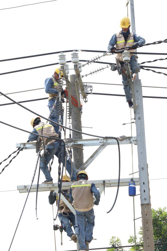
Electrical system blueprints include the installation locations of devices like outlets, switches, and lights. The plumbing blueprints detail clean and wastewater piping diagrams, along with placements of sanitary appliances and water treatment systems.
Electrical and plumbing systems are two foundational pillars in construction, ensuring the provision of not only electricity and water for daily use but also wastewater treatment, providing comfort and safety for users.
The plumbing system comprises the main components:
1. Water supply system:
- Water source: May be sourced from surface water, groundwater, or recycled water.
- Water supply piping: Transfers water from the source to the building through pumping stations.
- Pumping stations: Comprised of pumps, water tanks, and float devices to automatically cut off water.
- Distribution network: Connects from tanks to each area.
- Hot and cold water supply systems: Include direct or indirect cold water supply, and hot water through local systems or centralized systems like boilers, heat pumps, solar panels.
- Accessories: Include gate valves, butterfly valves, check valves, Y-filters, and joints.
2. Drainage system:
- Natural drainage (rainwater) and sewage drainage.
- Components like sewage pipes, siphons, and manholes.
- The wastewater piping system is designed to prevent blockages, frequently inspected and maintained.
- Ensure clarity between residential sewage and rainwater separation.
- Wastewater pipes include sewage, ventilation, and underground drains.
This system ensures high-quality water supply, efficient wastewater collection, and treatment, safeguarding health and the environment.
Electrical systems in construction projects:
- Supply electricity for lighting, daily activities, and machine operations.
- Include substation transformers, backup generators, electrical boards, wires, lighting, outlets, circuit breakers, and protective devices.
- Incorporate backup lighting and lightning protection for safety and continuity.
- Construction and maintenance must comply with technical and national standards.
Standards and regulations:
- National standards like TCVN 13606:2023, TCVN 4037:2012, TCVN 4038:2012, TCVN 7957:2008, TCXDVN 51:2008, and TCXDVN 33:2006 play a crucial role in design and construction.
Design and construction:
- System design requires schematic diagrams, identifying correct positions for components like tanks, pumps, and piping.
- Electrical systems need clear distinction between supply sources and distribution networks.
- Construction demands strict quality checks and regular maintenance to ensure stable operation.

3D Perspectives and Mapping Requirements
3D perspective offers a realistic view, aiding investors in visualizing the complete project. Occasionally, as-built maps are necessary to accurately represent the land location when legal documents lack coordinates.
Perspectives play an important role in construction and architecture projects. A 3D perspective image not only simulates the building’s three-dimensional space from various angles but also gives a comprehensive view of the design. This helps stakeholders, from investors to contractors, evaluate feasibility and clearly visualize position, style, and real-world dimensions in space.
Mapping and blueprint requirements in construction are indispensable. Types of maps like planning maps at scales 1/500, 1/2000, and 1/5000 are essential in planning construction. A 1/2000 scale map is typically used for detailed district planning, while the 1/500 scale document is mandatory for approving specific projects and even necessary for construction permits.
Moreover, location maps clearly define the land plot’s position and its relationship to neighboring areas. These must be conducted according to current standards and technical regulations, ensuring not only high precision but also legal validity.
Architectural blueprints provide a detailed view of the project’s overall structure, including floor plans, elevations, and cross-sections. These blueprints are essential documents for architectural designs and crucial in securing building permits and construction progresses. Especially, construction drawings must detail components from materials to field-processing and onsite construction instructions.
Architectural design must be accompanied by a complete design dossier, including basic design, technical design, and construction drawings. All must comply with national guidelines such as TCVN 5671:2012 and related legal regulations.
Lastly, important concepts like red line markers and building boundaries should be clearly defined in maps and blueprints to ensure land use rights and avoid potential legal issues.

The variety of blueprints in a factory construction permit application serves as key tools in ensuring technical feasibility, optimizing investment, and securing long-term project development strategies.
For more details and free consultation, please call QuangAnhcons at Hotline: +84 9 1975 8191.
QuangAnhcons offers professional consulting and preparation of construction drawing documentation, fully meeting all the requirements of high-quality industrial and construction projects.
[contact-form-7 id="7239967" title="Contact form 1"]
Related Posts
Substation Interconnection Documentation: A Practical Preparation Guide for Investors
A hands‑on guide for investors and M&E engineers on the information groups needed in substation [...]
May
Transformer Substation Construction Quote: Cost Components & Key Cost Drivers
Guidance for breaking down a transformer substation construction quote: main cost groups and the common [...]
May
Substation Solutions for Factories: Investing and Implementation Strategies
Overview of factory substations: when to invest, key components, execution processes, documentation, and selecting the [...]
Apr
Transformer Repair in Ho Chi Minh City: When Immediate Action Is Required
Discover signs of transformer damage, diagnostic methods, on-site handling processes, and criteria for selecting repair [...]
Apr
Transformer Repair: Process, Diagnosis, and Decision-Making
Hướng dẫn sửa chữa máy biến áp cho nhà máy: nhận biết dấu hiệu hỏng, [...]
Apr
24-Hour Transformer Repair: Efficient Solutions and Reliable Power Restoration
Khung xử lý sửa chữa máy biến áp 24h cho nhà máy: nhận biết sự [...]
Apr
Common Mistakes in Transformer Station Construction Leading to Extra Costs
Các sai lầm khi làm trạm biến áp thường không nằm ở một hạng mục [...]
Apr
Comprehensive Guide to Acquiring Used Transformers
Góc nhìn kỹ thuật về thu mua TBA cũ: cách đánh giá hiện trạng, hồ [...]
Apr
Comprehensive Transformers Maintenance for Industrial Plants
Tổng quan dịch vụ bảo trì trạm biến áp nhà máy: lịch bảo dưỡng, thí [...]
Apr
Transformers: Assessing and Safely Handling Used Transformers
Khung đánh giá máy biến áp cũ theo tình trạng kỹ thuật, dầu cách điện, [...]
Apr
How Proactive Transformer Maintenance Minimizes Business Risks
Nhìn từ góc độ vận hành nhà máy, bảo trì chủ động trạm biến áp [...]
Apr
Comparing Oil and Dry Transformers in Industrial Projects
Distinguish between oil and dry transformers based on installation site, safety, maintenance, energy losses, initial [...]
Mar
Electrical Overload Warning Signs in Factories
Recognize early indicators of factory electrical overload such as voltage drops, overheating equipment, circuit breaker [...]
Mar
Risks of Overloading Industrial Transformers Without Upgrades
Keeping the same low-voltage transformer while increasing factory loads can result in overheating, insulation degradation, [...]
Mar
Evaluating and Implementing Transformer Contractors in Tay Ninh
Criteria for selecting transformer substation contractors in Tay Ninh, EPC scope, and factors affecting project [...]
Mar
Comparing Oil and Dry Transformers for Industrial Applications
Examine oil and dry transformers based on installation location, fire safety, maintenance, energy loss, investment [...]
Mar
Comprehensive 1500kVA Transformer Station Budget for Manufacturing Facilities
Guidance for creating a detailed budget list for a 1500kVA transformer station, including medium voltage [...]
Mar
Comprehensive Transformer Station Pricing: Elements and Considerations
Examine key components in comprehensive transformer station pricing including design, equipment, construction, testing, and connection [...]
Mar
Pricing Guide for 4000kVA Transformer Stations: Configuration, Cost, and Investment Process
An overview of configuration, cost estimates, connection approaches, and investment checklists for 4000kVA transformer stations [...]
Mar
Pricing and Setup of 3200kVA Transformer Stations: Configuration, Costs, and Investment Procedure
Explore the pricing structure for a 3200kVA transformer station, primary equipment configuration, cost variables, EVN [...]
Mar