- Common Causes of PV System Damage
- Field Assessment and Electrical Safety Procedures
- Testing Methods: EL, IV Curve, and Thermography
- IEC/UL/NEC Standards and Insurance Requirements
- Damage Classification by Module, Inverter, BOS, and Structure
- Technical Reports and Corrective Recommendations
- Environmental Risks and Safety Precautions
Our solar damage assessment service includes identifying damage causes, field assessment procedures, using EL testing, IV curve measurement, and infrared thermography; complying with IEC/UL/NEC standards; classifying damage by module, inverter, BOS, and structure; creating detailed reports and corrective action recommendations while ensuring safety.
Common Causes of PV System Damage
The solar damage assessment service focuses on identifying key cause groups: (1) Environmental and operational factors like storms, lightning, flooding, high temperatures, hail, and strong winds causing mechanical damage to modules, cables, and inverters; (2) Specific physical phenomena including PID (Potential Induced Degradation), hot spots, and microcracks that reduce performance and cause module degradation; (3) Installation and maintenance faults such as loose connections, improper wiring, rodent damage, insulation aging, DC arc faults from insulation failure, and non-standard connectors; (4) Auxiliary equipment like overheating inverters, external circuit failure, ground faults, and moisture-induced issues; (5) Physical impacts on modules like cracks, scratches, and moisture ingress causing corrosion and electrical safety risks. This forms the basis for systematic PV failure surveys.
Many PV projects operate under harsh conditions, so identifying the root causes of solar system issues optimizes the safety, performance, and lifespan of the setup.
1) Environmental and Operational Conditions
- Storms, strong winds: Repeated mechanical stress leading to module and frame deformation, loosening of bolts/connections, affecting DC/AC cables and inverter over time [2][8].
- Lightning: Can trigger DC arc faults causing fires at connections, cables, and electrical equipment [1][2][6][7].
- Flooding: Moisture ingress through panel seams, connectors, or enclosures leading to electrochemical corrosion, lifespan reduction, short circuits, and leakage [2][5].
- High temperatures: Overheating inverters, increasing hot-spot risk on modules, reducing performance/lifespan, and contributing to insulation failures and discharges [3][6].
- Hail: May crack/break glass, damage cells and busbars, affect lamination structure, reducing efficiency or damaging modules [1][8].
2) Specific Physical Phenomena of Modules
- PID (Potential Induced Degradation): Efficiency loss due to voltage drop between module and ground, causing local discharges—partially reversible with specialized techniques. PID evaluation combines electrical measurement and time-related effects [4].
- Hot-spot: Caused by shading, soldering faults, or microcracks leading to local heating; reduces lifespan and may cause module fires [1][4].
- Microcrack: Tiny cracks in cells that develop over time, reducing power output; often undetectable by the naked eye [4].
- LID/Light Soaking: Initial efficiency drop due to light-induced degradation areas—partially recoverable with Light Soaking [4].
- Snail trails: Stains from oxidation or adhesive faults, usually accompanying microcracks [4].
- Delamination: Separation between module layers, weakening mechanical strength and reducing efficiency [8].
- Yellowing/UV degradation: UV-induced EVA discoloration reducing light transmission efficiency [8].
- Soiling: Dust build-up reducing cell illumination and output [4].
- PID-Recovery: Partly reversible PID effects with specialist treatment [4].
3) Installation and Maintenance Faults
- Loose connections: Increase contact resistance, cause DC arcs, hot spots, and fire risks [1][2][3].
- Improper wiring: Possible short circuits, inverter fires, or overall efficiency loss [1][9].
- Improper torque settings: Prone to loosening over time, increasing discharge risks and reducing mechanical stability [1][8].
- Electrochemical corrosion: Moisture, oxygen, or chemicals damaging connectors, cables, and devices [2][5].
- Moisture ingress at cables/connectors: Common source of DC arc faults, electrical leaks, and shorts [2][5].
- Rodent damage to cables: Causes breaks, signal loss, or short circuits [2].
- Insulation aging: Insulation resistance decreases over time, increasing leakage and short-circuit risks [5].
- DC arc-fault: Arcs from faulty connections or components, potentially leading to system fires [1][2][6].
4) Auxiliary Equipment Failures
- Overheating inverter: From high ambient temperatures or overloads, may trigger shutdowns or inverter failure [3][5].
- MPPT fault: Incorrect maximum power point tracking causing output losses [5].
- DC/AC circuit faults: Circuit element failures causing voltage loss or abnormal operation [5].
- Ground fault: Loss/faulty grounding causing leakage, fire risks, and device damage [5][7].
- PID due to polarity voltage difference: System polarity issues potentially leading to PID [4].
- Moisture/condensation in enclosures: Component oxidation, short circuits, and electronic lifespan reduction [5].
- Surge/OV/UV: Over/under-voltage or surge can destroy inverters and components; appropriate SPD deployment is needed [1][6].
5) Physical Impacts on Modules
- Glass cracks, cell cracks: Due to pressure or impacts (like hail), reducing power output and lifespan [1][8].
- Hail impact: Tested per IEC 61215 for hail resistance evaluation [8].
- Tempered glass: Enhances load capacity and durability against environmental stress [8].
- IEC 61215/61730: PV module standards on environmental, mechanical, and safety requirements [8].
- Damaged busbars/ribbons: Loss of current-carrying paths in cells, reducing efficiency [4].
- Lamination voids: Structural weaknesses increasing moisture ingress and degradation [4].
6) Diagnostic and Evaluation Methods
- IV curve tracing: Measurement of I-V characteristics for module/string performance evaluation [4][8].
- EL (Electroluminescence) testing: Detects microcracks and hidden defects [4][8].
- IR thermography: Thermal imaging identifies hot-spots and abnormal heating points [4].
- Drone inspection: Efficient aerial surveillance for large-scale projects [8].
- PR/PR loss comparison: Monitoring Performance Ratio for system degradation detection [4][8].
- String-level monitoring: Individual string monitoring for early array fault warnings [4][8].
- Insulation resistance test (MEGGER): Measures insulation resistance to detect electrical leakage [5].
- Hi-Pot test: High voltage withstand testing of insulation [5].
- Surge test: Surge wave testing for SPD/devices before overvoltages [6].
- Impedance spectroscopy: Analyzes impedance to identify electrochemical or internal fractures [4].
7) Standards and Recommendations Related
- IEC 61215, IEC 61730, IEC 61646: Design, safety, and durability of PV modules [8].
- IEC 62920, IEC TS 63126: Requirements for high-temperature conditions [4].
- IEC 60364-7-712: AC/DC electrical system requirements for PV [4].
- IEC 62446-1: Testing, inspection, and guidance for PV systems [4].
- UL 1741/9540: Safety standards for inverters and energy storage systems (ESS) [4].
- NEC, NFPA 70, IEEE: Standards/regulations for solar electrical systems design and safety [4].
8) Risk Mitigation Measures
- Lighting protection, SPD: Install suitable SPD for surge/overvoltage protection [1][6].
- Drainage design: Prevent localized flooding and moisture ingress [2][5].
- Enhanced IP rating, sealing: Choose environment-compatible protection devices, seal against moisture/dust [2][5].
- UV-resistant materials: Minimize aging on plastic enclosures and connectors due to UV exposure [4][8].
- Proper cable clamps/trays: Protect cables from physical impact and corrosion [2][5].
- Standard torque settings: Ensure stable, long-term fastening force, preventing loosened connections [1][8].
- Periodic checks: Detect anomalies early and address them promptly [4][5].
- Condition monitoring: Online continuous performance monitoring and early failure warnings [4][8].
Adopting a systematic approach from cause identification to diagnosis, standards, and mitigation enables businesses to proactively manage risks, limit solar power system incidents, and optimize long-term operational outcomes.
Field Assessment and Electrical Safety Procedures
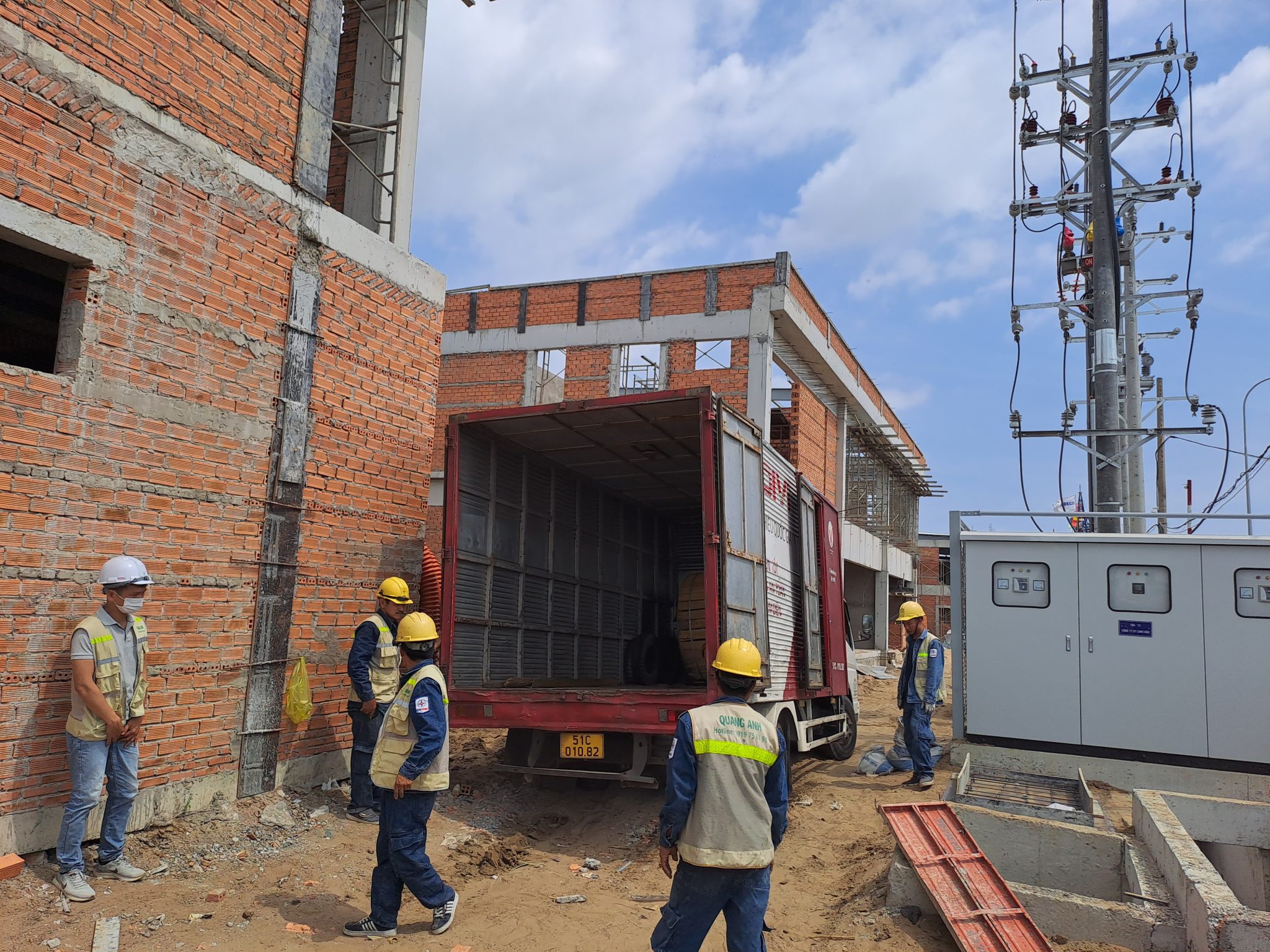
Our solar damage assessment service involves a comprehensive on-site process including: visual inspections of modules, structures, connections, glass surfaces, and lightning protection systems; electrical safety checks such as insulation resistance, grounding, leakage, and arc fault risks; and recording operational statuses. This solar inspection process ensures reliable data for cause and impact analysis while maintaining personnel and equipment safety via power isolation, use of insulated tools, and adherence to electrical safety testing protocols.
Scope and Objectives
Post-incident PV system evaluations form the foundation for identifying damage extent and restoring operational safety. The process focuses on visual checks, electrical safety examinations, compliant to IEC/NEC standards, and comprehensive measurement documentation to develop remediation suggestions.
Visual On-Site Examination
- PV Modules: Inspect for cracks, broken glass, delamination, and PID signs affecting performance. Conduct IEC 62446-1 thermographic imaging to detect hot spots and poor contact points, forming a critical part of on-site PV evaluations to preempt potential risks.
- Supporting Frameworks and Structures: Evaluate corrosion, deformation, and mechanical damage; inspect connections, bolts, welds for moisture ingress or rust potentially weakening system durability.
- Junction Boxes and Cable Connections: Assess connectors and boxes for moisture, oxidation, or loose fit causing shorts; monitor DC/AC cables, trays, conduits for cuts, scratches, thermal aging, or rodent attacks.
- Lightning and Overvoltage Protection Systems: Review PV lightning systems per IEC 62305; check surge protection devices (SPD) per IEC 61643, evaluating current operational effectiveness.
Technical Electrical Safety Checks
- Insulation Resistance Measurement: Conduct megohmmeter testing per IEC 62446-1 to ensure cable and module insulation resistance meets safety thresholds (typically > 1 MΩ). This measurement is mandatory in post-incident electrical safety inspections.
- IV Curve, Open Circuit Voltage/Short Circuit Current (Voc/Isc): Measure and compare IV characteristics per IEC 61215 with manufacturer specifications to identify performance reductions.
- Grounding and Protective Earth (PE): Measure earth resistance within permissible limits (e.g. < 100 Ω depending on the system) and check PE wire continuity to prevent leakage.
- Leakage and Arc Detection (AFCI): Use arc fault detection equipment to identify and isolate dangerous leakage or shorting incidents.
- Comprehensive Thermal Imaging: Following IEC 62446-1, capture thermographic images of PV modules, junction boxes, cabling to reveal hot spots and defective connections. This supports on-site PV evaluations with quantitative evidence and image-based verification.
Field Safety Protocols
- Power Isolation: Disconnect PV and inverter sources, employing Lockout-Tagout (LOTO) to ensure no power is supplied during the inspection.
- Personal Protective Equipment (PPE): Equip with appropriate electrical insulation protection, gloves, glasses, and helmets suitable for the risk level.
- Safety Distance: Adhere to IEC 60364-7-712 and NEC 690 when working near powered equipment. Critical requirement for on-site electrical safety inspections.
Applicable Standards
- IEC 62446-1:2016 – Inspection and testing requirements for grid-connected PV systems, including IV curve, insulation resistance measurement, infrared imaging, and installation acceptance records.
- IEC 60364-7-712:2017/2025 – PV installation regulations, ground fault protection, earthing, electrical safety, and conditions for electrical work.
- NEC Article 690 – PV safety requirements: signs, protection, power isolation, voltage limits, overcurrent protection.
- IEC 61215, IEC 61730 – Reliability, performance, and electrical-mechanical safety of PV modules.
- IEC 62305, IEC 61643 – PV lightning protection systems and surge overvoltage protection devices (SPD).
Post-Incident Inspection Procedure
- Isolate and ensure safety: LOTO, PPE, power down inverters and PV arrays.
- Visual examination: Modules, support structures; inspect for glass cracks, delamination; PV thermographic imaging to detect hot-spots.
- Review junction and connector boxes, DC/AC cabling, cable trays, conduits: Search for damage signs, moisture, oxidation, leakage.
- Compare PV lightning systems and SPD: Check effectiveness, related earth resistance measurement.
- Measure insulation and electrical parameters: Voc, Isc, IV curve, insulation resistance and PE continuity per IEC 62446-1.
- Check for leakage, arcing: Use AFCI equipment to identify and isolate faults.
- Record thermal data: Capture imagery of module clusters, junction boxes, cables.
- Data Collection: Store SCADA, inverter logs, imagery, and field notes.
- Create reports: Clearly document conditions, safety check results, and repair suggestions.
This procedure ensures comprehensive PV field assessments with complete evaluation evidence adhering to international standards.
Model Content of Inspection Reports
- Customer, project information; date, personnel involved.
- PV system description: capacity, number of modules, inverters.
- Results from visual inspection, PV thermographic imaging, and hot-spot detection.
- Insulation resistance, IV curve, Voc/Isc results; earth resistance and PE continuity results.
- Identification of arcs/leakages (AFCI) and impact level.
- Remediation proposals, repair recommendations signed by the inspector and investor.
Adherence to IEC 62446-1, IEC 60364-7-712, NEC 690, IEC 61215, IEC 61730, IEC 62305, and IEC 61643 ensures transparent, consistent PV field inspections prioritizing electrical safety, providing a robust technical foundation for post-incident recovery.
Testing Methods: EL, IV Curve, and Thermography
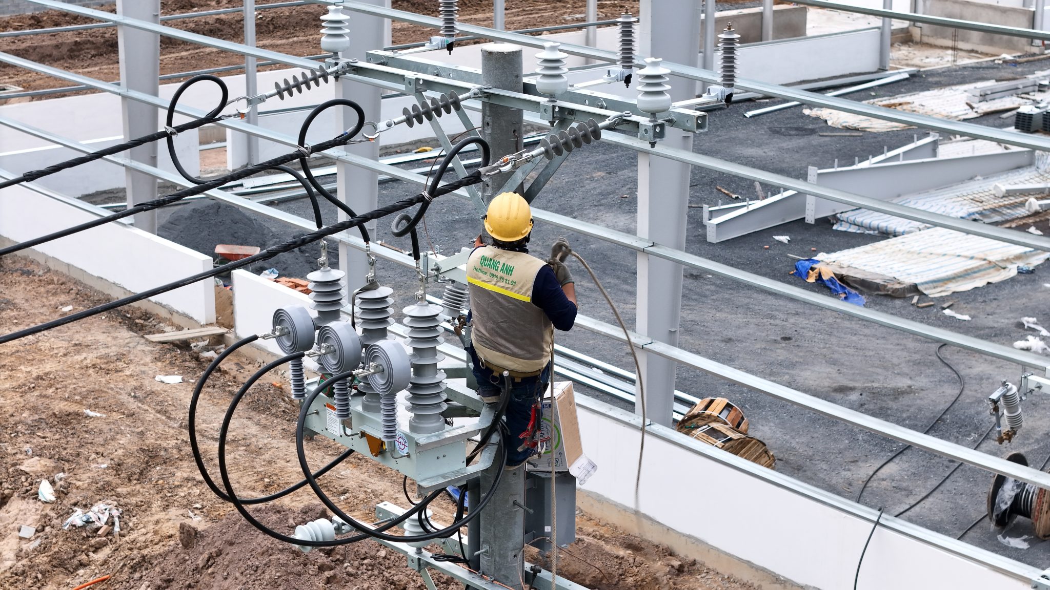
Our solar damage assessment service employs standard tools: (1) EL module testing for microcracks, inactive spots, and hidden cell degradation; (2) IV curve measurement to detect power drops, and circuit faults in standard conditions; (3) infrared thermal imaging for identifying hot spots, module overheating, faulty connections that pose shorting or fire risks. Integrating EL, IV curve, and thermography provides precise impact quantification and rapid cause localization.
Conducting module and PV string quality evaluations requires a coordinated measurement procedure, combining EL PV inspection, IV curve PV analysis, and PV thermography according to current IEC standards like IEC 62446, ensuring replicability, comparability, and diagnosis of solar panel PID, microcracks, or connection issues.
Electroluminescence (EL) Testing for PV Modules
- Principle: Applying currents through PV cells causes carrier recombination which emits photons in the infrared/near-infrared range. EL images display bright-dim areas indicating material quality and defects such as microcracks, dead zones (inactive), fractured fingers/busbars, cell mismatches, or PID signs.
- Equipment: A DC source applies rated currents/voltages; CCD/CMOS cameras with infrared sensitivity or specialized cameras with suitable wavelength filters; dark environments or light shielded chambers to minimize optical noise.
- Procedure:
- Laboratory: apply standard currents (often near Isc), capture high-resolution EL images for material and defect analysis.
- Field: utilize portable equipment, control ambient light, adjust stimulation currents, specify exposure times; standardize module temperature, current, ambient lighting.
- Relevant IEC Standards: IEC 60904-11 specifies EL measurement methods; IEC 61215 and IEC 61646 guide module durability and defect testing, where EL serves as an effective tool.
- Common EL Image Issues:
- Microcracks: isolated dark spots potentially progressing over time.
- Cell mismatch: uneven bright-dark cell patterns.
- PID: localized dimming from efficiency declines.
- Fractured fingers/busbars: dark lines along conductor paths.
- Inactive/dead cells: large non-emitting dark regions.
- Error Factors: Ambient light, module temperature, stimulation currents, exposure times, and angles may skew signal strength or distort images.
IV Curve Tracing for PV Modules/Strings
- Measurement Standards: IEC 60904 covers photovoltaic cell electrical standards; IEC 60891 guides data corrections to STC conditions (1000 W/m², 25 °C, AM 1.5G) for accurate IV curve PV comparisons.
- Analytical Parameters:
- Voc (open-circuit voltage), Isc (short-circuit current), Pmax (maximum power).
- Fill Factor (FF) = Pmax / (Voc × Isc), indicating curve “squareness”.
- Error Identification via IV Curves:
- Power loss: Pmax reduction compared to baseline data or similar modules.
- Series faults: lower voltage; parallel (shunt) faults: reduced current.
- Shading: deforms the curve, creating localized breakpoints.
- Bypass diode behavior: reflected by the negative voltage slope characteristic.
- Conductive losses: assessed through string voltage/current drop.
- Measurement Practice: Perform under stable radiation and temperature; separate strings/modules for comparison; correct data to STC via IEC 60891 for precise IV curve PV analysis.
Infrared Thermography for PV
- Standards and Scope: IEC TS 62446-3 and IEC 62446 specify equipment, measurement conditions, and methods for hotspot detection, delamination, PID, junction box, or MC4 connection overheating.
- UAV Surveying: Utilizes drones to cover large areas; requires surface emissivity calibration, viewing angle adjustment, flight height, and measurement frequency for consistent thermal maps in PV thermography.
- Error Recognition on Thermal Images:
- Hot-spots: abnormal temperature points due to cell/connection faults.
- Delamination: areas of layer separation displaying temperature differences.
- PID: non-uniform hot areas.
- Overheating at junction boxes/connections: localized temperature rise.
- Influencing Error Factors: Emissivity changes due to dust/contamination; wind surface cooling effects; viewing angle and flight conditions affecting readings; un-calibrated procedures may cause discrepancies of several degrees Celsius.
Combining EL + I-V + IR for Cause Localization and Impact Quantification
- Objective: Differentiate module (cell, laminate) faults from BOS (connections, cabling, inverter) errors; evaluate at cell-level to system-level.
- Investigation Procedure:
- IV Measurement: capture current, voltage, power, series-parallel error models, shading impacts.
- EL Imaging: locate microcracks, dead cells, mismatches, PID signs at cell-level.
- IR Imaging: detect hot-spots, connection overheating for safety risk assessment.
- Data Compilation: cross-verify EL patterns, IV curve data, and thermal images to attribute faults to modules or BOS.
- Report Compilation: include illustration, performance data, impact assessment, and remediation recommendations.
- Field Best Practices:
- Standardize measurement conditions, calibrate equipment per IEC 60904 (EL, I-V) and IEC 62446 (PV thermography, system checks).
- Record environmental conditions (temperature, radiation, wind) and cross-check equipment pre/post-measurements.
- Utilize specialized software to process EL/IR imagery and I-V data, ensuring traceability and temporal comparisons.
Integrating EL PV inspections, IV curve analyses, and deploying PV thermography under the IEC 62446 framework and related standards accelerates diagnosis time, enhances reliability in issue attribution, and provides clear technical bases for maintenance and repair planning in systems at risk of PID or connection failures.
IEC/UL/NEC Standards and Insurance Requirements
Our solar damage assessment services align with international standards: IEC 61215 and IEC 61730 for PV module quality and safety; IEC 62817, UL 1703, and NEC 690 for system installation and safety evaluations. Detailed technical assessment reports provide a basis for insurers to determine causes, extent of damage, and claim valuation for modules, inverters, BOS systems, and structures. Applying standards ensures solar inspection results are consistent, transparent, and acceptable within claims processes.
Applicable Standards Framework in PV Damage Assessment
- IEC 61215: Reference for assessing PV module-related quality when examining damage and degradation.
- IEC 61730: Safety requirements framework for PV modules to review safety risks in damage assessments.
- IEC 62817, UL 1703, NEC 690: Standards/codes used for system installation and safety requirements, ensuring installation conditions align with widely recognized technical criteria.
Assessment Scope and Coverage
- PV Modules: Reference against IEC 61215 and IEC 61730 examining quality and safety issues when losses occur.
- Inverters: Included within evaluations to identify cause and impact of damage related to electrical conversion.
- BOS Systems: Comprehensive system support elements shape the influence and valuation foundation for claims.
- Structures: Record conditions and environmental impacts compiled within claims-supporting reports.
Technical Reporting for Insurance Evaluation
- Determine Causes: Clarify damage causes relating to the PV module, inverters; BOS and structural aspects.
- Quantify Damage Extent: Delineate item-specific impact to support valuation stages.
- Compensation Valuation: Constructed based on technical evaluations and recorded damage scope.
Standard Application Principles in Inspections
- Adherence to outlined standards (IEC 61215, IEC 61730, IEC 62817, UL 1703, NEC 690) to ensure inspections follow internationally accepted criteria.
- Consistent, transparent presentation of inspection results aligns with insurer review requirements.
- Installation and safety system condition comparison against related standards enhances report reliability in claims procedures.
Report Presentation Methodology
- Standard-specific: PV module evaluations based on IEC 61215 and IEC 61730; installation, system safety content contrasted with IEC 62817, UL 1703, and NEC 690.
- Asset-specific: Module, inverter, BOS system, and structural content described separately for cause, damage extent, and valuation basis.
- Insurance-focused: Content structured directly for determining causes, impact scope, and compensation foundation.
Damage Classification by Module, Inverter, BOS, and Structure
Damage Classification by Module, Inverter, BOS, and Structure
The solar damage assessment service distinctly categorizes: Module – glass cracks, microcracks, hot-spots, PID, performance reduction; Inverter – overheating, connection faults, grounding loss, circuit failure; BOS – damaged cables, connectors, junction box, electrical leakage; Structure – breaks, deformation from storms, lightning, mechanical stress. This classification prioritizes actions based on risk and asset value, aiding focused PV damage surveys and efficient repair/replacement planning.
This equipment-grouped approach allows systematic PV damage evaluations concentrating on vulnerable areas and optimizing repair/replacement decisions. This way, survey scope, resource allocation, and system downtime are managed based on risk and asset value, avoiding indiscriminate management.
Grouping Principles for Quick Localization
- Modules: Group phenomena causing degradation and defects at panel and string levels, forming a basis to prioritize module repair based on production and array stability impacts.
- Inverters: Concentrate on disruptions in conversion and anomalies regarding protection/grounding, facilitating inverter fault identification and correction within system-wide impact scopes.
- BOS: Encompasses DC/AC cabling, connectors, and junction boxes; grouping aids swift BOS fault localization and elimination of leak/disruption points in cabling corridors.
- Structures: Monitor deformation, breaks, and linkage issues due to environmental impacts; grouping demarcates necessary structural reinforcements or localized replacements.
Priority Based on Risk and Asset Value
- Priority 1: Items posing widespread or major disruption risks, directly impacting safety and high-value assets; prioritize isolation and immediate correction.
- Priority 2: Items with moderate effects on production or stability, handled as groups to optimize downtime.
- Priority 3: Items with limited impact, scheduled for routine maintenance and performance trend monitoring for future replacement decisions.
This arrangement ensures all groups are assessed but resources are concentrated where risks and asset values are highest, aligned with targeted PV damage assessment goals.
Field Survey Application and Remediation Planning
- Localization: Rapidly identify affected equipment groups (modules, inverters, BOS, structures) for suitable team assignment; facilitating separation of module damage, inverter issues, BOS faults, and structural damage, avoiding overlaps.
- Structured Recording: Categorize by groups, positions, and impact levels; aggregate data forms a comprehensive view of the entire system supporting targeted PV damage evaluations.
- Planning: Develop repair/replacement lists per priority; optimize downtime and intervention scope by device clusters to expedite recovery time.
Long-Term Operational Value
- Repeatability: Consistent classification frameworks maintain report quality across surveys, simplify comparisons and monitoring.
- Cost Optimization: Focus on significant impact points first, avoiding resource wastage on low-impact items.
- Transparent Decision-Making: Repair/replacement actions aligned with specific risk and asset values offer clear technical bases for approval.
By maintaining consistent classification across four equipment groups, project teams can expedite PV damage evaluation processes, keep focused on-field investigations, and develop substantiated, safety-continuity-efficiency oriented recovery plans.
Technical Reports and Corrective Recommendations
The solar damage assessment service compiles reports including fault descriptions, cause analysis, EL data, IV curves, and thermal images with illustrative comparisons to standards. Corrective recommendations: replace damaged modules, repair connections/cables, enhance grounding, add surge protection devices, implement a regular maintenance schedule. Safety reminders: disconnect power before assessments, use insulated equipment, control leakage to prevent further damage. Reports act as technical evidence for insurance and operation planning.
Report Scope and Methodology
Technical reports are built around two content groups: (i) Quantitative technical evidence comprising EL data, IV curves, and thermal imaging with illustrative commentary; (ii) Qualitative analysis based on fault descriptions, cause evaluation, and standards comparison. This approach ensures each assessment is data-backed and traceable.
Field Data Collection and Presentation
- EL: Record data for identifying cell-level abnormalities, present as images with annotations to facilitate comparison.
- IV Curves: Measure, store characteristic curves reflecting string/asset operating statuses, shown graphically for easy comparisons.
- Thermal Imaging: Capture and label observation positions to identify heat generation areas, accompanied by illustrative imagery for clarity.
All data files are linked to fault descriptions, ensuring a connection between observed phenomena and related equipment categories.
Cause Evaluation and Standards Comparison
Analysis focuses on linking fault descriptions with EL, IV curve, and thermal imaging data. Comparison results with applicable standards are documented to establish technical bases for assertions. Presentation emphasizes consistency: measurement data, illustrations, and technical arguments must align.
Corrective Recommendations by Impact Level
- Replace damaged modules to remove risk sources and restore stable power generation.
- Repair connections/cables upon detecting connectivity issues or insulation deterioration.
- Enhance grounding to boost operational safety and reduce system fault risks.
- Add surge protection for improved overvoltage defense.
- Implement routine maintenance following plans to control repetitive risks and sustain performance.
Each recommendation relates directly to corresponding measurement evidence for convenient decision-making and execution.
Safety Controls During Implementation
- Cut power before inspections to ensure safe operations.
- Use insulation-specific tools to limit short circuit risks.
- Monitor for electrical leakage to avoid compounding device damage during assessments.
These safety notes apply throughout surveys, inspections, and data recording.
Report Utility as Technical Evidence
Reports provide technical evidence supporting insurance claims and serve as inputs for operational planning. Focusing on fault descriptions, cause evaluation, attached EL data, IV curves, and thermal imaging with visuals accelerates decision-making while forming a basis for corrective and routine maintenance.
Environmental Risks and Safety Precautions
Solar damage assessment services identify key risks: storms, lightning causing structural damage and arc faults; PID, hot-spots reducing efficiency; microcracks spreading; water/flooding, high humidity reducing insulation, increasing leakage and explosion risk; poor installation/operation shortening lifespan. Risk control recommendations are based on IEC/UL/NEC compliance and regular inspections with thermal imaging, IV measurements, and EL module testing to detect issues early, minimizing losses and interruptions.
The solar damage assessment service clarifies correlations between risk groups and early detection methods, creating control frameworks aligned with IEC/UL/NEC compliance and disruption reduction strategies.
Extreme Weather: Storms, Lightning Impact on Systems
Storms and lightning may damage structures or trigger arc faults. For such risks, prioritizing IEC/UL/NEC compliance during on-site assessments and regular inspections for timely abnormality detection is crucial.
- Control measures: Conduct regular thermal imaging, IV measurements, EL module testing per inspection plans.
- Goals: Early detection of structural damage, arc issues, minimizing losses and interruptions.
Efficiency Reduction Risks: PID, Hot-spots, Microcracks
PID and hot-spots reduce efficiency; microcracks may spread over time, affecting operations. Periodic inspections to detect these discrepancies early for prompt resolution are utilized.
- Thermal imaging detects heat abnormalities related to hot-spots.
- IV measurements assess efficiency reductions.
- EL module inspection identifies structural discrepancies like microcracks.
Our solar damage assessment service deploys these practices collectively to limit expansive impacts and maintain effective system utilization.
Water, Flooding, and Electrical Safety
Water ingress and humidity lower insulation, increasing leakage and explosion risks. Regular inspections as recommended and IEC/UL/NEC compliance are central to managing electricity safety risks in wet environments.
- Apply thermal imaging, IV measurements, EL module testing for early anomaly detection.
- Prioritize identification of electrical leaks and insulation decreases to mitigate explosion risks.
Installation/Operation Mistakes and Lifespan Effects
Installation or operation mistakes can reduce system lifespan. The focus is quality control through IEC/UL/NEC adherence and routine inspection maintenance to spot deviations early.
- Periodically check thermal imaging, IV measurements, EL modules to find operational anomalies.
- Timely response to minimize losses and avoid prolonged disruptions.
Risk Control Framework Implementation
- Identify risk groups: storms/lightning; PID and hot-spots; microcracks; water/humidity; installation/operation errors.
- Establish compliance processes with IEC/UL/NEC fitting project scope and safety requirements.
- Apply regular inspections: thermal imaging, IV measurements, EL module testing for early anomaly detection.
- Focus on loss and disruption minimization by processing inspection results.
When applied consistently with IEC/UL/NEC standards and the mentioned periodic inspection schedule, solar damage assessment services help promptly identify risks, reduce performance losses, and maintain system continuity.
Solar damage assessment services offer a technical advantage through precise EL, IV, and thermal diagnostics; an investment benefit by categorizing damage by components to optimize repair/replacement costs; and a strategic edge as reports adhere to IEC/UL/NEC standards, meet insurance requirements, and support maintenance planning.
Need to implement Solar Damage Assessment Services for your project? Contact QuangAnhcons – Hotline: +84 9 1975 8191 to schedule surveys and receive technical reports.
QuangAnhcons provides comprehensive solar damage assessment services, covering damage cause identification; field assessment and electrical safety processes; technical testing with EL module examination, IV curve measurement, and infrared imaging; IEC/UL/NEC standard compliance checks; damage classification by module, inverter, BOS, and structure; detailed report compilation with corrective recommendations and safety guidelines.
[contact-form-7 id="7239967" title="Contact form 1"]

Related Posts
Tay Ninh Solar Power Planning: Technical Framework, Grid Interconnection, and Rollout Roadmap
Technical overview of solar planning in Tay Ninh: irradiation, grid capacity, permitting, design, operations, and [...]
Dec
Binh Duong Solar Planning: Regulatory Framework, Grid Interconnection, and an Implementation Roadmap for Factories and Industrial Parks
An overview of Binh Duong solar planning: legal framework, interconnection, design, risk management, and an [...]
Dec
Solar Farm Repair: O&M Workflow, IV Curve Diagnostics, Thermography, Inverter Service and Utility-Scale Safety
A utility-scale solar farm repair plan centered on O&M, IV curves, thermal imaging, inverter service, [...]
Dec
Dong Nai Solar Power Plan 2023–2025: Tri An 1,029 MW, Grid Upgrades and the DPPA Pathway
A complete look at Dong Nai’s solar power plan: Tri An 1,029 MW, irradiation potential, [...]
Nov
Quang Ngai Solar Power Plan 2024–2030: Legal Framework, Irradiance Potential, and Development Roadmap
A complete look at Quang Ngai’s solar power plan: capacity targets, irradiance (PVout), development zones, [...]
Nov
Solar Damage Assessment Services: On-Site Procedures, EL/IV/Thermography Testing & Compliance with Standards
Discover IEC/UL/NEC standard solar damage assessment processes: on-site evaluation, EL and IV curve testing, thermal [...]
Nov
Comprehensive Package Estimate for a 1800MVA 500kV Substation: Scope, Configuration 3x600MVA, Standards and Timeline Management
An overview of the 1800MVA 500kV substation estimate: construction scope, configuration 3x600MVA, GIS/AIS, SCADA, standards, [...]
Nov
Factory Electrical Systems: Comprehensive Design and Implementation Guide
Discover the detailed and safe process of factory electrical systems design and implementation. [...]
Oct
Blueprints Required for Factory Construction Permits
Discover the necessary blueprints in factory construction permit applications, from floor plans to electrical and [...]
Oct
What Are the Requirements for a Factory Construction Permit? A Comprehensive Guide
Explore the documentation and steps needed to secure a factory construction permit for streamlined project [...]
Oct
Factory Construction Permit Procedures in Vietnam: Essential Guidelines and Documents
Learn the procedures for securing a factory construction permit in Vietnam, focusing on document preparation [...]
Oct
Key Steps in the Factory Construction Process
Discover the essential steps and requirements for building factories. [...]
Oct
Comprehensive Electrical Substation Solutions by Quanganhcons
Discover the cutting-edge electrical substation solutions offered by Quanganhcons for industrial applications. [...]
Oct
Investment Costs for a 1MWp Solar Power System and Influencing Factors
Explore the investment costs for a 1MWp solar power system in Vietnam and the influencing [...]
Sep
QuangAnhcons: Elevating Wind Energy Solutions
Explore QuangAnhcons' leadership in wind energy and renewable solutions in Vietnam. [...]
Sep
Electrical Contractor Strategies at Becamex Industrial Park
Discover the strategic advancements and partnerships of the electrical contractor at Becamex Industrial Park. [...]
Sep
Investment Insights for 1MW Wind Energy in Vietnam: Costs and Opportunities
Discover the detailed analysis of costs and opportunities for investing in 1MW wind energy projects [...]
Sep
Advanced Electrical Installation Solutions by QuangAnhcons
Explore advanced electrical installation solutions and modern technology with QuangAnhcons. [...]
Sep
Enhancing Industrial Electrical Services with Quanganhcons
Discover Quanganhcons' expertise in industrial electrical services, offering efficient and sustainable power systems. [...]
Sep
Comprehensive MEP Solutions by QuangAnhcons: From Design to Maintenance Excellence
Discover optimal MEP solutions with QuangAnhcons, dedicated to excellence from design through maintenance. [...]
Sep