


A corporate EV depot needs an electrical infrastructure brief before it needs a charger purchase order. For an FDI factory in Vietnam, the brief should connect fleet energy needs to the permitted supply capacity, physical installation boundaries, control responsibilities and commissioning evidence. A list of charger ratings does not tell the owner whether the site can support the new operation or which package must close a missing interface.
This guide addresses the electrical data room and scope allocation for a return-to-base corporate fleet. It is not a charging-service guarantee, an equipment recommendation or a construction design. Numerical examples are explicitly hypothetical. No vehicle, client, price, project approval or QuangAnhcons installation outcome is implied.
Prepared for QuangAnhcons · Editorial focus: FDI depot electrical infrastructure and procurement interfaces · Sources checked: 14 October 2026.
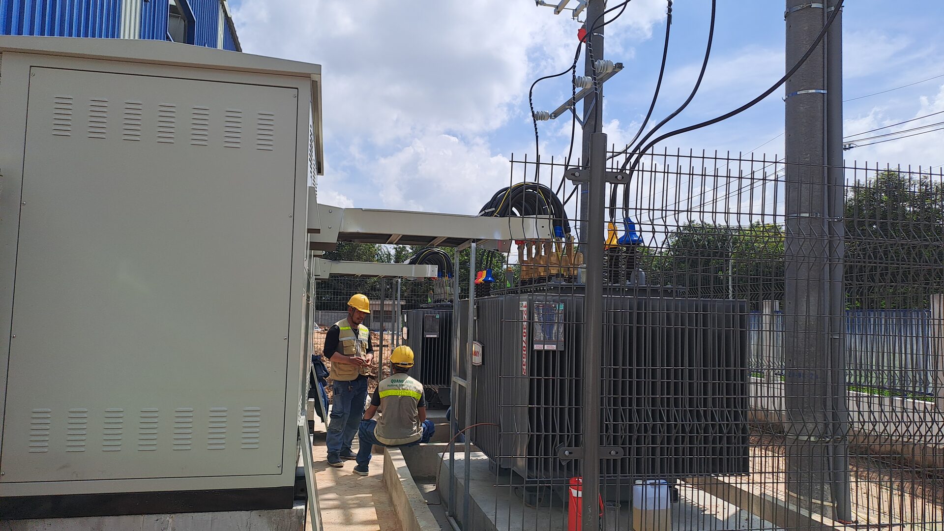
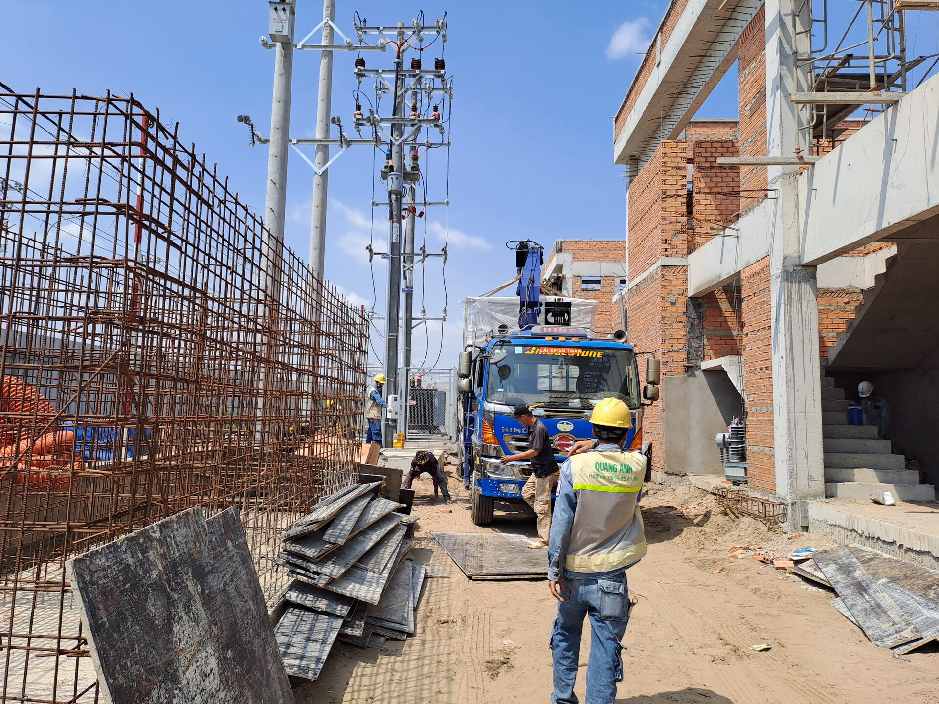
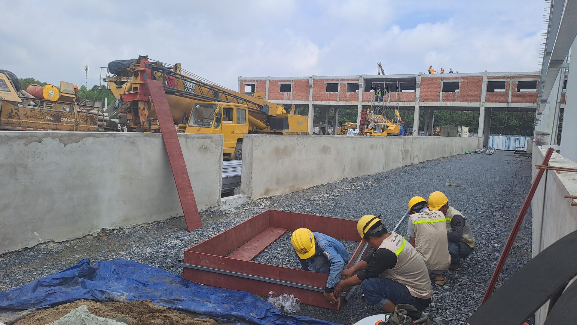
Featured photograph: QuangAnhcons electrical-project field archive, used for equipment-delivery interface context. It is not a photograph of the hypothetical corporate EV depot or evidence of a completed depot installation.
1. Start with the operating basis, not the number of charging pedestals
Ask the fleet operator for vehicle groups, duty patterns, return windows, required energy replenishment and expansion stages. Distinguish battery nameplate capacity from energy that must actually be restored after a route. Record whether the supplied energy value is measured at the AC supply, charger DC output or vehicle battery. Mixing these boundaries can make a depot appear feasible when its electrical input requirement is understated.
The vehicle OEM should confirm connector compatibility, accepted charging modes, voltage range, charging curves, temperature limits and any fleet-management restrictions. An AC vehicle’s onboard charger can constrain the usable charging rate even when the pedestal has a higher nameplate rating. For DC charging, vehicle demand and charging taper still matter. The brief should require matching evidence for the exact vehicle and charger combination rather than assume that two ratings with the same unit imply compatibility.
Operational information has an engineering purpose: it sets the time window in which energy can be delivered and the overlap of load. It does not itself define a contractual departure-readiness service level. That is a separate operating agreement. The electrical package should return an auditable capacity and connection model with clearly stated operating assumptions.
The US Department of Energy fleet planning guidance provides a useful planning checklist for vehicle needs and infrastructure compatibility. Its jurisdiction-specific certification, incentive and electrical-system examples are not Vietnamese requirements. This article uses only the general planning method.
2. Show the depot on the existing electrical single-line diagram
The functional connection is: utility or industrial-park supply → factory transformer and main switchboard → dedicated EV feeder → depot distribution and isolation → individual EV supply equipment → vehicles. The PCC meter and controller signals are information paths, not power conductors. The concept diagram must also locate any PV, BESS, generator, ATS and bus tie that can change available supply or fault conditions.
Mark the proposed connection point, property boundary, revenue-metering boundary and operational switching authority. These may be different locations. In a leased factory, the landlord may own the transformer while the tenant procures the chargers. A contractor cannot resolve that distinction by calling the job “turnkey.” Ask who approves the connection, releases an outage, maintains each asset and accepts the final load cap.
| Input | Evidence to request | Decision it supports |
|---|---|---|
| Serving entity and capacity | Applicable supply agreement, written capacity conditions and connection correspondence | Whether new demand or a network change is permitted |
| Transformer and switchboard | Controlled SLD, nameplates, assembly ratings, protective-device data and maintenance condition | Whether existing equipment can support the proposed operating cases |
| Existing loads | Time-aligned measurements with interval, missing-data flags and production states | Available headroom, not nominal unused kVA alone |
| Cable route and installation | Survey lengths, installation method, grouping, environment, crossings and access constraints | Detailed cable design and civil interfaces |
| Fault and earthing basis | Maximum/minimum fault cases, topology, earth/PE records and protection settings | Breaking duty, fault clearing and shock-protection design |
| Vehicle/EVSE pair | Exact model manuals, revisions, connector and charge-curve evidence | Equipment interoperability and operating limits |
A spare breaker position is not proof of spare transformer capacity, acceptable voltage drop, suitable fault rating or a compliant charging circuit. Conversely, a high sum of charger nameplates does not automatically require all chargers to draw their maximum simultaneously. A controlled operating envelope can change the load case, but its effectiveness and failure behaviour must be demonstrated.
3. Use an energy–power screening calculation before promising a solution
Hypothetical example, not a design or a quotation: assume 24 vehicles each need 40 kWh restored at the charger DC output during an eight-hour overnight window. Assume a charger conversion efficiency of 0.92 at the relevant duty and 3 kW of depot auxiliaries throughout the window. These values are teaching inputs, not prescribed factors, actual fleet data or OEM claims.
| Parameter | Illustrative value | Must be replaced by |
|---|---|---|
| Vehicles / DC energy per vehicle | 24 / 40 kWh | Qualified route and charging records |
| Charging window | 8 h | Actual arrival, departure and connection availability |
| DC-output / AC-input efficiency | 0.92 | Model-specific duty-dependent evidence |
| Separate auxiliaries | 3 kW | Defined metering boundary and measured equipment needs |
| Available total depot AC cap | 90 kW | Approved capacity and verified electrical study |
The fleet needs 24 × 40 = 960 kWh at DC output. The corresponding charger AC energy is 960 / 0.92 = 1,043.48 kWh. Separate auxiliaries add 3 × 8 = 24 kWh. The minimum average depot AC input is therefore (1,043.48 + 24) / 8 = 133.43 kW.
At a hypothetical total depot limit of 90 kW, only 87 kW remains for charger input after auxiliaries. Even with ideal continuous use, the maximum DC output energy over eight hours would be (90 − 3) × 8 × 0.92 = 640.32 kWh. The shortfall is 960 − 640.32 = 319.68 kWh. Installing more chargers does not remove that energy deficit. It may improve access or redundancy, but cannot increase the energy available through the same enforced supply cap.
An independent reverse check gives the minimum ideal window: 960 / (87 × 0.92) = 11.994 h, approximately 12 hours. For a six-hour window, the ideal average AC requirement rises to 960 / (0.92 × 6) + 3 = 176.91 kW. These are lower-bound screens: delayed returns, taper, unavailable connectors, maintenance and interruptions can make the real requirement more demanding.
If an illustrative aggregate true power factor of 0.98 and a balanced 400 V three-phase input are additionally assumed, 133.43 kW corresponds to approximately 136.16 kVA and 196.53 A. This arithmetic does not select a breaker, cable or transformer. Phase allocation, harmonics, corrected cable ampacity, voltage drop, short-circuit maximum/minimum, protection coordination and equipment thermal limits remain unverified. Do not use this current as an approved feeder rating.
The owner now has a meaningful decision: change the energy/window assumptions, qualify more electrical capacity, stage fleet deployment or investigate an independently engineered alternative. BESS can shift energy delivery, but needs a charging opportunity and its own capacity, controls and safety study. Midday PV cannot be credited as overnight supply without a supported time-shifting arrangement.
4. Define control authority and the failure envelope
When a depot shares supply with production, describe the measured factory-load boundary and which controller limits EV power. Define meter update rates, timestamps, communications, unavailable-data handling and the party authorised to change settings. Do not allow an energy dashboard, charger cloud portal and factory EMS to compete for dispatch authority without an agreed hierarchy.
A safe fallback limit must be derived from the actual site and approved design. This guide supplies no universal fallback kW setting. The RFQ should require the vendor to explain behaviour after loss of the PCC meter, local controller, WAN connection, charger communications or time synchronisation. Cloud loss need not mean electrical protection loss, but that separation must be demonstrated rather than advertised.
Specify separately emergency isolation, normal charging stop, maintenance isolation and loss-of-supply recovery. An application stop command is not a physical isolation procedure. Electrical work must follow the site’s approved permit, lockout/tagout, stored-energy and verification arrangements, performed by competent authorised personnel. No switching sequence or energized-work method is provided here.
Also identify data ownership. The fleet operator may need vehicle-session records; the facility team needs demand and alarm history; the landlord may need only aggregated metering. Ask for retention, export format, role access, time alignment and a supported exit from the software provider. Protocol names alone do not prove interoperability with the selected backend and firmware.
5. Keep legal, standards, utility and OEM evidence in separate registers
For conductive charging equipment, IEC 61851-1:2017, Edition 3, with Corrigendum 1:2023, identifies the general EV supply-equipment scope. For installation circuits, IEC 60364-7-722:2018, Edition 2 addresses supplies for electric vehicles. These are different boundaries: equipment evidence does not replace completed-installation verification.
The public IEC catalogue pages were read for identifiers, editions and scope, not licensed clauses. No residual-current rating, clearance, cable derating or test limit is attributed to an unread standard. The selected designer must review the controlled editions required by the project and identify the applicable clauses before equipment is released.
| Layer | Document / edition | Use and access limit |
|---|---|---|
| Vietnam law / QCVN | Project-specific legal and safety applicability register | Responsible project professionals must identify current documents, transitions and approval scope; this article does not establish a permitting route or blanket compliance. |
| TCVN equipment reference | TCVN 13078-1:2020, conductive charging systems, general requirements | Official national-register search result identifies the document and title; direct page fetch timed out on 14 October 2026. No full-text, active-status, clause or project-applicability claim is made. The designer must verify the controlled national editions and the separate installation basis. |
| IEC EVSE | IEC 61851-1:2017 + COR1:2023 | Official catalogue scope accessed 14 October 2026; not evidence that a proposed product is certified. |
| IEC installation | IEC 60364-7-722:2018 | Official catalogue scope accessed 14 October 2026; selected project edition requires controlled review. |
| Serving entity | Specific utility or industrial-park conditions | Capacity, metering, protection and switching requirements must come from the actual serving entity, not a generic “EVN compliant” statement. |
| OEM / project | Exact vehicle, EVSE, protective device and controller manuals | No model selected here. Return revisions and performance boundaries with the bid. |
Factory approvals and public retail charging are not automatically the same project. Ask the legal and facility teams to classify the actual use, ownership and operating arrangement. Do not import US subsidies, wiring practices or licensing procedures from the cited DOE planning material into a Vietnamese tender.
6. Issue one RFQ matrix so bidders price the same interfaces
The following return schedule is more useful than asking three vendors for “24 chargers.” Provide controlled drawings and a missing-data register, then require every bidder to mark included, excluded, provisional and owner-supplied items. Bidders should name dependencies instead of quietly treating unresolved work as another party’s scope.
| Package | Required bid return | Acceptance interface |
|---|---|---|
| Survey and design | Data gaps, assumptions, study register, existing/proposed SLD and connection boundary | Owner approves basis before procurement release |
| Electrical supply | Upstream changes, feeder/DB scope, protection/earthing studies and outage needs | Serving entity, landlord and factory switching authority |
| EVSE and vehicles | Exact models, compatibility matrix, charge curves, limits and approved configuration | Vehicle OEM and charger integrator |
| Civil and logistics | Foundation reactions, drainage, traffic protection, route crossings and delivery access | Civil designer, fleet operations and safety team |
| Controls and ICT | Meter/EMS integration, dispatch hierarchy, failure-state matrix and data export | Factory controls and IT/security acceptance |
| Testing / handover | Inspection plan, functional test cases, controlled settings, training and support | Documented owner release and operations acceptance |
Use the factory P/Q load-schedule guide for consolidating existing and new loads, and the fault-case register for maximum and minimum electrical cases. The design responsibility matrix helps allocate owner, designer, OEM and installation decisions. These are supporting methods, not a substitute for depot-specific records.
Require separate priced allowances for survey, design, supply, civil work, installation, integration, testing and operating support. No indicative price or market lead time is offered here. Every commercial offer needs currency, VAT treatment, scope, exclusions, validity and the owner’s actual procurement conditions.
Compare bid deviations at the electrical boundary
An international procurement team may receive a charger OEM offer, a local installation offer and an EPC offer against the same brief. Their totals are not comparable until the accepted data baseline and interface responsibilities are aligned. A site-survey checklist cannot close that commercial gap. Return one deviation schedule alongside the technical proposal, with the drawing revision, responsible party, unresolved input, priced assumption and procurement hold point for each boundary.
Consider three hypothetical bid positions, without invented prices. Bid A excludes all upstream modifications but assumes that the owner supplies adequate power. Bid B includes an EV distribution board and feeders, yet excludes connection approval and a factory outage. Bid C includes the interface studies but keeps equipment quantities provisional until the vehicle and layout data are frozen. None is inherently the best or worst offer. The owner must determine which exclusions are supported by verified data, who will complete the omitted work and whether the resulting operating envelope meets the tender requirement.
| Bid assumption | Evidence needed before acceptance | Owner disposition |
|---|---|---|
| Existing supply is adequate | Accepted load/capacity study and actual serving-entity conditions | Accept only a qualified baseline; keep an unresolved upgrade as a named dependency |
| Factory shutdown is owner-supplied | Approved access window, switching authority and integration boundaries | Allocate planning and release; do not treat an assumed outage date as a commitment |
| Cloud controls enforce the load cap | Supported local architecture, fallback narrative and testable failure cases | Separate normal software functions from protective and isolation functions |
| Vendor certification covers the complete depot | Exact product evidence plus installation design/verification deliverables | Reject the blanket claim; list the system-level evidence still required |
| Charger performance meets the fleet requirement | Model/vehicle compatibility and the accepted energy/window calculation | Do not substitute peak nameplate kW for the operating requirement |
Turn accepted deviations into a controlled contract baseline through the owner’s authorised procurement process. This article does not amend contract obligations or provide legal advice. Keep technical input ownership separate from commercial responsibility: the fleet operator supplies qualified duty data, the serving entity supplies its applicable connection conditions, the designer establishes the electrical basis, the OEM supplies equipment limitations, and the integrator demonstrates the agreed interfaces.
For each promised output, ask which evidence can be supplied at bid stage and which must be delivered after award. A signed supplier statement is not the same as a completed site test. An OEM declaration may support equipment identification, while an installed load-cap function still needs a system test at the accepted meter boundary. Define which party witnesses the test, who can release the hold point, how unresolved results are recorded and what work may proceed while a safety-critical item is open.
Require a versioned handover baseline across the overseas OEM and the Vietnam installation team. Include model and firmware identifiers, drawings, accepted configuration, alarm meanings, data exports, translated operating instructions where the facility team needs them and the support escalation path. Do not put passwords or live network topology in a public RFQ. The value of this return schedule is not more paperwork: it exposes a supply or control assumption before a purchase order makes that assumption expensive to change.
7. Use hold points and a testable handover dossier
A compact WBS starts with operating-basis approval, then survey/data qualification, connection and study review, procurement release, coordinated civil/electrical work, pre-energisation inspection, functional tests and handover. Procurement release follows approved equipment/interface data; civil work can overlap only where interfaces are frozen. Energisation follows the authorised pre-energisation hold point. Durations and critical path are not calculated because no project calendar, delivery commitments or approval durations are known.
Functional testing should demonstrate the agreed load cap, meter failure, communications failure, controller restart, power restoration and interactions with factory production. Use a documented test boundary and safe approved procedure. A screenshot of a cloud dashboard is not sufficient evidence of an enforced site limit. Keep electrical safety acceptance separate from the fleet operating trial.
Handover should include controlled SLDs, cable/DB schedules, study outputs, protection settings, OEM manuals and revisions, inspection records, test datasets, accepted software configuration, alarm/fallback matrix, access credentials handed over securely, operator training and support responsibilities. Record unresolved items with owner and due date; do not label the installation fully accepted while safety-critical conditions remain open.
Before issuing the depot tender: send the fleet energy/window data, controlled factory SLD, load measurements, site layout, supply correspondence and target operating date for a scope review. Close the missing capacity, ownership and control questions before comparing equipment prices. That approach gives procurement an electrical brief that bidders can price and facility teams can verify.
Sources and limits
Official IEC catalogue pages above support only publication metadata and scope. The DOE infrastructure procurement checklist was consulted for planning and package coordination, not US legal obligations or quoted costs. The national TCVN register fetch limitation is disclosed. All calculations are original arithmetic using stated hypothetical inputs; no coefficient is presented as a prescribed design factor, no model has been selected, and no technical or legal certification is claimed.
[contact-form-7 id="7239967" title="Contact form 1"]Substation budget estimate
Select the capacity, route lengths and package to view your indicative budget and electrical parameters.
Request a project quotation
Send your project details, BOQ or drawings to request a formal quotation. Fields marked * are required.
Quotation scope
Applies to one EVN-supplied substation with oil-immersed transformers at 22/0.4 kV (single-phase: 12.7/0.23 kV), with MV metering VTs/CTs supplied by EVN. The estimate includes the selected equipment, installation, earthing, transformer-to-main-breaker connections, design and connection documentation, and coordination of testing and utility acceptance.
Kiosk, integrated steel-pole and indoor substations include MV switchgear and the entered underground cable route. Other outdoor arrangements use the relevant protection configuration. The final diagram must meet the project connection requirements.
Excludes VAT, cables from the substation switchboard to the MSB/loads, live-line work, harmonic reactors, weak-ground treatment or special piling, land and special fire-protection provisions. Underground routes assume normal construction conditions and exclude road drilling and special reinstatement.
Prices are indicative investment budgets. A formal quotation follows site assessment and agreement on the configuration. Electrical selections are preliminary and require design verification before installation.
Capacity range and application conditions
The catalogue defines the enquiry range of this tool, not universal TCVN capacity limits. Single pole-mounted transformers: 15–100 kVA; three-unit banks: 3×15–3×100 kVA. Platform substations: 100–630 kVA. Steel-pole substations: 100–630 kVA; 750/800 kVA require design verification and local approval. Ground-mounted, kiosk and indoor configurations: 50–10,000 kVA. Not every configuration has a package price or the same structural design.
Reference: EVN Decision 1299/QD-EVN dated 3 November 2017, Volume 1, sections 3.3–3.4. Check the current requirements of the responsible utility before implementation. Kiosks must meet manufacturer ratings and testing requirements (IEC 62271-202); indoor and ground-mounted arrangements must meet project layout, ventilation, structural and fire-protection requirements. For multiple transformers, specify the quantity and capacity of each unit.
Developed by QuangAnhcons · © 2026 QuangAnhcons. Code licensed under GPL-2.0-or-later. Standards and manufacturer data belong to their respective owners.
Related Posts
Corporate EV Depot Electrical Brief: Supply, Interfaces and RFQ
Prepare a corporate EV depot electrical brief for Vietnam: qualify supply capacity, energy boundaries, control [...]
Oct
Comprehensive Cost Guide for Constructing a Dual-Pillar 60kW Fast EV Charging Station by QuangAnhcons
In the age of sustainable transportation, the demand for efficient and rapid electric vehicle (EV) [...]
Apr
Integrating Fire Safety in EV Charging Station Construction
As society moves toward greener alternatives, electric vehicles (EVs) stand at the forefront of efforts [...]
Mar
The cost of the grounding system for an EV charging station
Creating a robust EV charging station involves not just the right technology for charging vehicles, [...]
Mar
How much does the low-voltage electrical system for an EV fast-charging station cost?
Quanganhcons is at the forefront of delivering comprehensive low-voltage electrical supply and installation services for [...]
Mar
The cost of supplying and installing the low-voltage electrical cables for a 60kW dual EV charging station
The Low-Voltage Electrical Cable Installation for EV Chargers When it comes to the foundation of [...]
Mar
How much does it cost for two 60kW DC fast chargers in Vietnam?
Pioneering Fast-Charging Infrastructure: The Installation of Dual 60kW DC EV Chargers Investing in the electrification [...]
Mar
Cost-Effective Electrical Panel Installation for EV Charging Stations
Electrical Panel Installation: The Financial and Technical Backbone of EV Charging Stations The cost of [...]
Mar
The cost of the construction process for a 160kVA substation in building a fast-charging EV station in Vietnam
The 160kVA Transformer Station: Powering Up High-Speed EV Charging In the quest to electrify transportation, [...]
Mar
Fast charging EV station construction cost – EV charging infrastructure Vietnam
The cost of the basic excavation and construction process in building a fast-charging EV station [...]
Mar